Tape dispenser

Inactive Publication Date: 2005-11-03
HENKEL CORP
View PDF24 Cites 9 Cited by
  • Summary
  • Abstract
  • Description
  • Claims
  • Application Information

AI Technical Summary

Benefits of technology

[0014] Still another object is the provision of a tape dispenser of the foregoing character which enables the application of a run of tape fully into a corner between adjacent right angle surfaces and the cutting or tearing of the tape such as to accurately fill the corner in the direction of application.
[0015] A further object is the provision of a hand manipulable dispenser for a roll of tape in which a brake

Problems solved by technology

This process is not only time consuming and cumbersome in that it most often requires the withdrawal and re-application of the tape to the underlying surface in an effort to control the position of the tape edge along the adjacent surfaces.
Moreover, this process makes it extremely difficult if not possible to maintain the tape edge straight and to avoid the occurrence of gaps between the tape edge and the adjacent surface.
Such difficulties result from the instability of application caused by the user's one hand holding the tape roll and the other hand attempting to press the dispensed tape into place and the application of a varying pulling force on the tape roll during the tape applying procedure which is caused by the tape roll being handheld and thus grasped with different holding forces by the user during the application process.
Another problem encountered in connection with the taping of ad

Method used


Image

  • Tape dispenser
  • Tape dispenser
  • Tape dispenser

Examples


Embodiment Construction

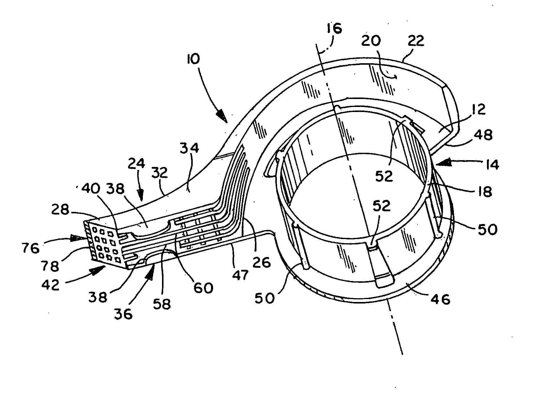
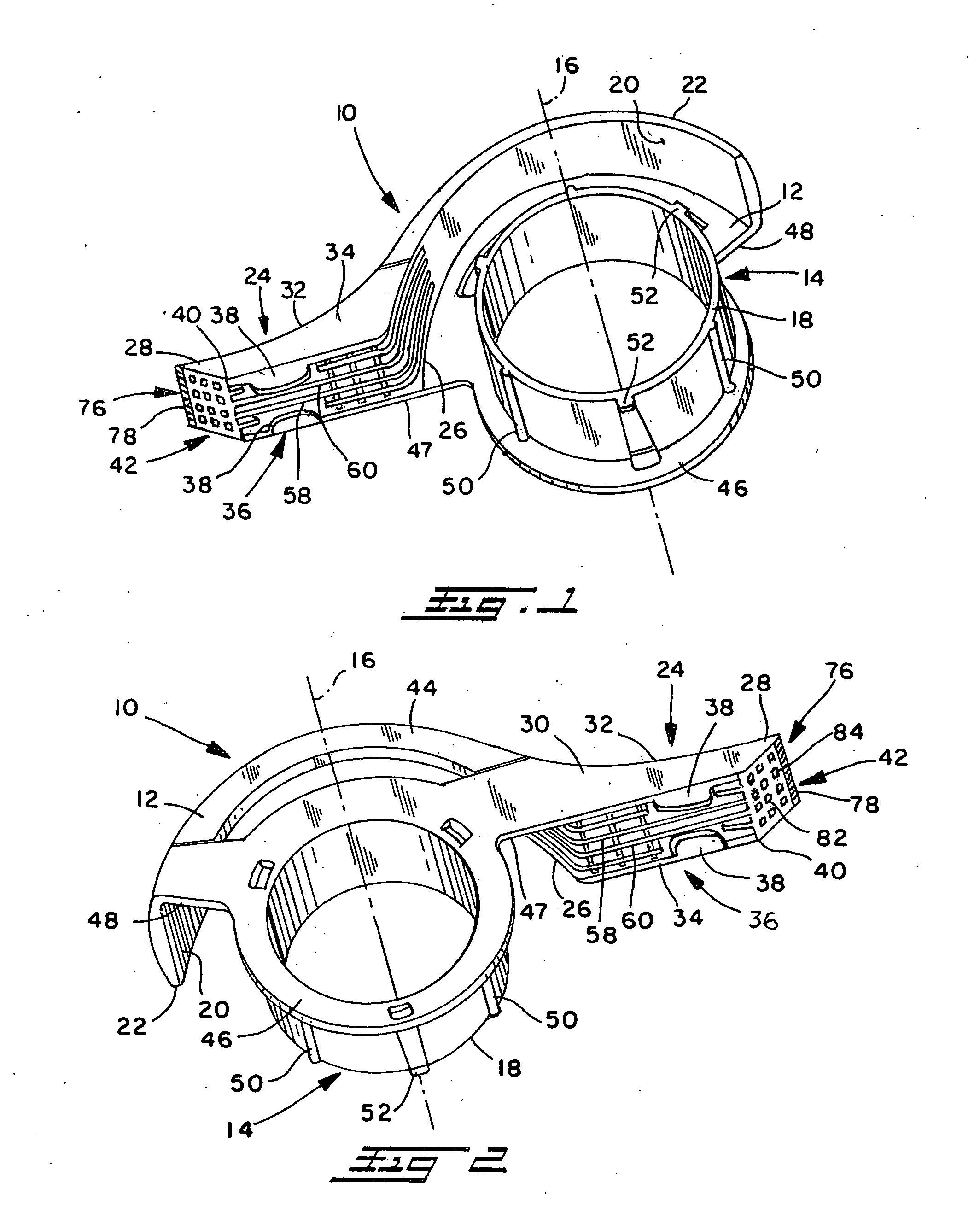
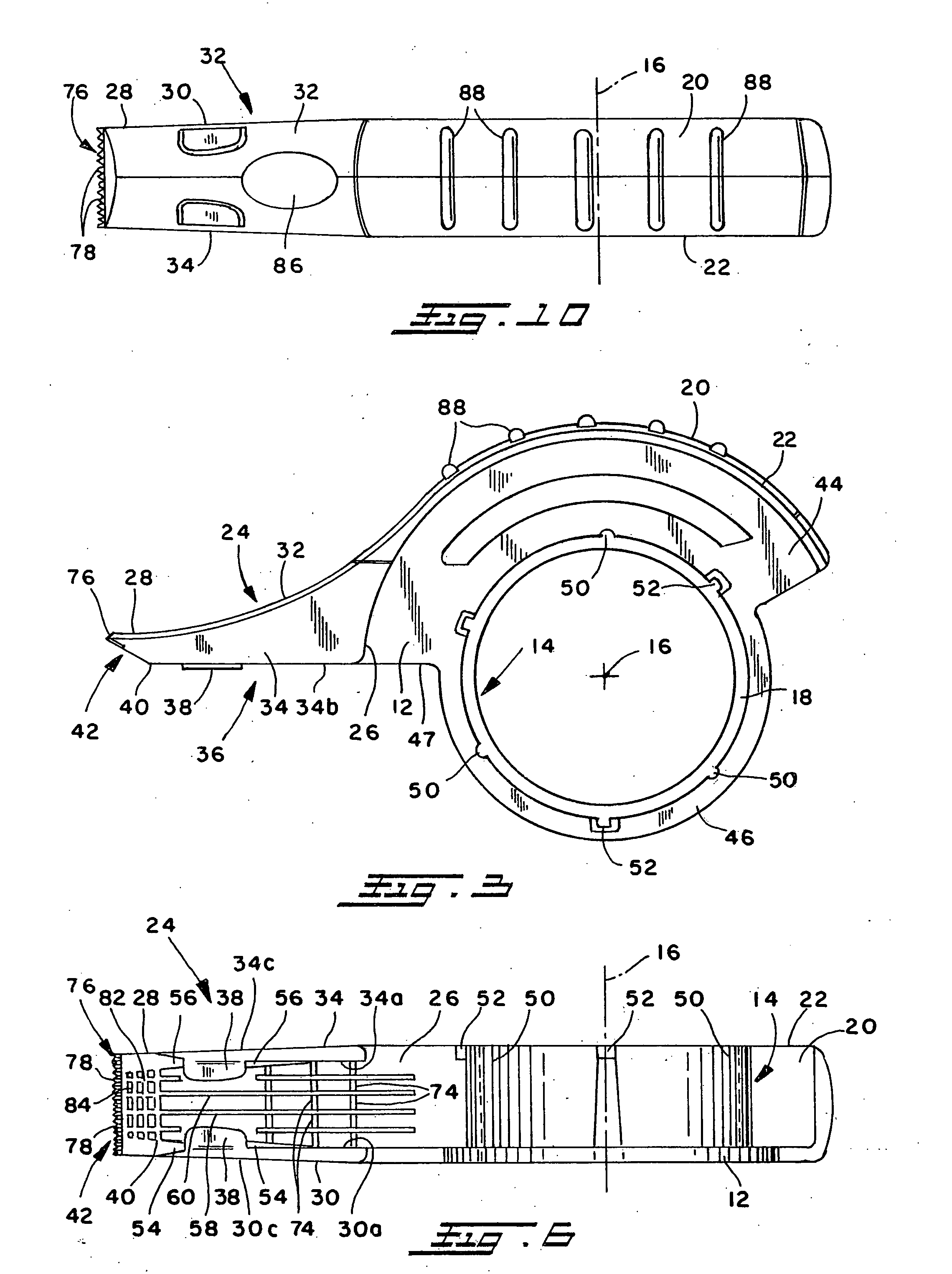
[0031] Referring now in greater detail to the drawings wherein the showings are for the purpose of illustrating preferred embodiments of the invention and not for the purpose of limiting the invention, a tape dispenser and applicator 10 in accordance with the present invention is produced from a suitable plastic material and includes a planar wall 12, a tape roll support in the form of an annular hub 14 extending transverse to wall 12 and having an axis 16 and an axially outer end 18 spaced from wall 12 a distance slightly greater than the width of a roll of tape to be mounted thereon. The dispenser further includes an arcuate wall 20 radially spaced from hub 14 a distance generally corresponding to and at least slightly greater than the radial thickness of a roll of tape to be mounted on the latter. Wall 20 extends transverse to planar wall 12 and has an axially outer end 22 generally axially coextensive with outer end 18 of hub 14. The dispenser further includes a dispensing arm 2...


PUM


Abstract

A tape dispenser comprises a cylindrical hub for rotatably supporting a roll of tape, and a dispensing arm extends radially outwardly of the hub and has a tape guide on the bottom thereof by which tape is arched concavely toward an underlying surface as the tape is displaced from the dispenser and applied to the underlying surface. A brake arrangement on the dispenser is operable manually by a user to stop or otherwise control rotation of a tape roll during a dispensing operation.

Description

BACKGROUND OF THE INVENTION [0001] This invention relates to the art of tape dispensers and, more particularly, to an improved tape dispenser which can be manipulated to apply a tape along a path with improved control of the dispensing and the location of an edge of the tape relative to the path. [0002] The present invention finds particular utility in connection with the dispensing of masking tape and the application of such tape along the juncture between angularly related surfaces such as a window pane and a frame or mullion to be painted and, accordingly, will be disclosed and described herein in detail in connection with such use. At the same time, however, it will be appreciated that the dispenser can be used with tapes other than masking tape and in connection with the application of tape to any surface or along the juncture between adjacent angularly related surfaces with improved control of the location of an edge of the tape along the path of movement during the applicatio...

Claims


Application Information

Patent Timeline
IPC IPC(8): B65H35/00
CPCB65H35/0033B65H2402/412Y10T156/1795Y10T156/1348Y10T156/18Y10T156/1365Y10T156/1788Y10T225/269Y10T225/294
Inventor VAN TYLE, PETER R.FERGOT, DAVID L.MARTINEZ, JOSE M.
Owner HENKEL CORP
Why Eureka
Try Eureka