Controllable flow resistance in a cooling apparatus

a technology of controllable flow and cooling apparatus, which is applied in the direction of light and heating apparatus, machines/engines, air heaters, etc., can solve the problems of less effective heat transfer from equipment to cooling airflow, significant heat generation of electronic equipment contained within the enclosure, and thermal damage to electronic equipmen

Active Publication Date: 2005-11-03
HEWLETT-PACKARD ENTERPRISE DEV LP
View PDF26 Cites 110 Cited by
  • Summary
  • Abstract
  • Description
  • Claims
  • Application Information

AI Technical Summary

Problems solved by technology

Electronic equipment contained within the enclosure generates a significant amount of heat.
Thermal damage may occur to the electronic equipment unless the heat is removed.
If airflow patterns allow re-usage of air that is previously heated by electronic equipment component to attempt to cool electronic equipment, less effective heat transfer from the equipment to the cooling airflow can result.
In some circumstances insufficient heat transfer can take place and the equipment may overheat and potentially sustain thermal damage.
One re-circulation scenario occurs when a fan fails and hot air exhausted from other vents in the system may re-circulate back to the vicinity of the failed fan, greatly impacting thermal management for device.

Method used


Image

  • Controllable flow resistance in a cooling apparatus
  • Controllable flow resistance in a cooling apparatus
  • Controllable flow resistance in a cooling apparatus

Examples


Embodiment Construction

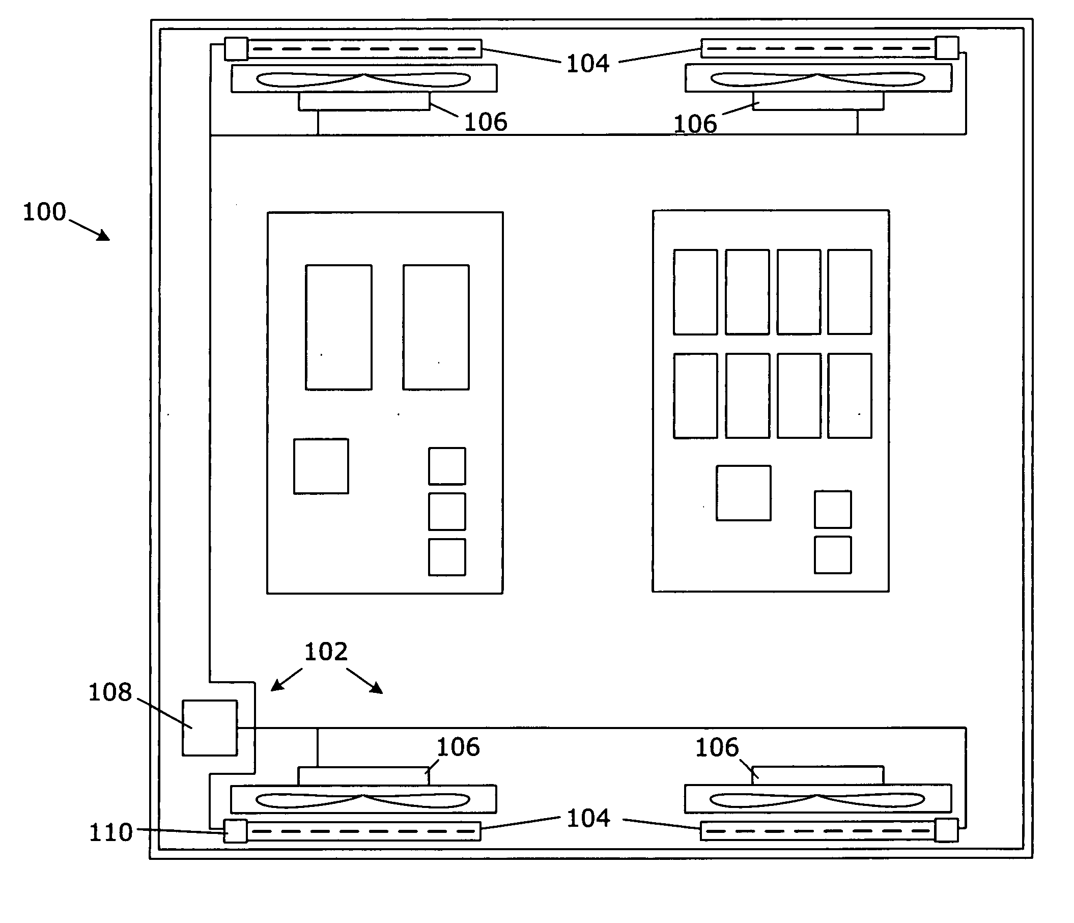
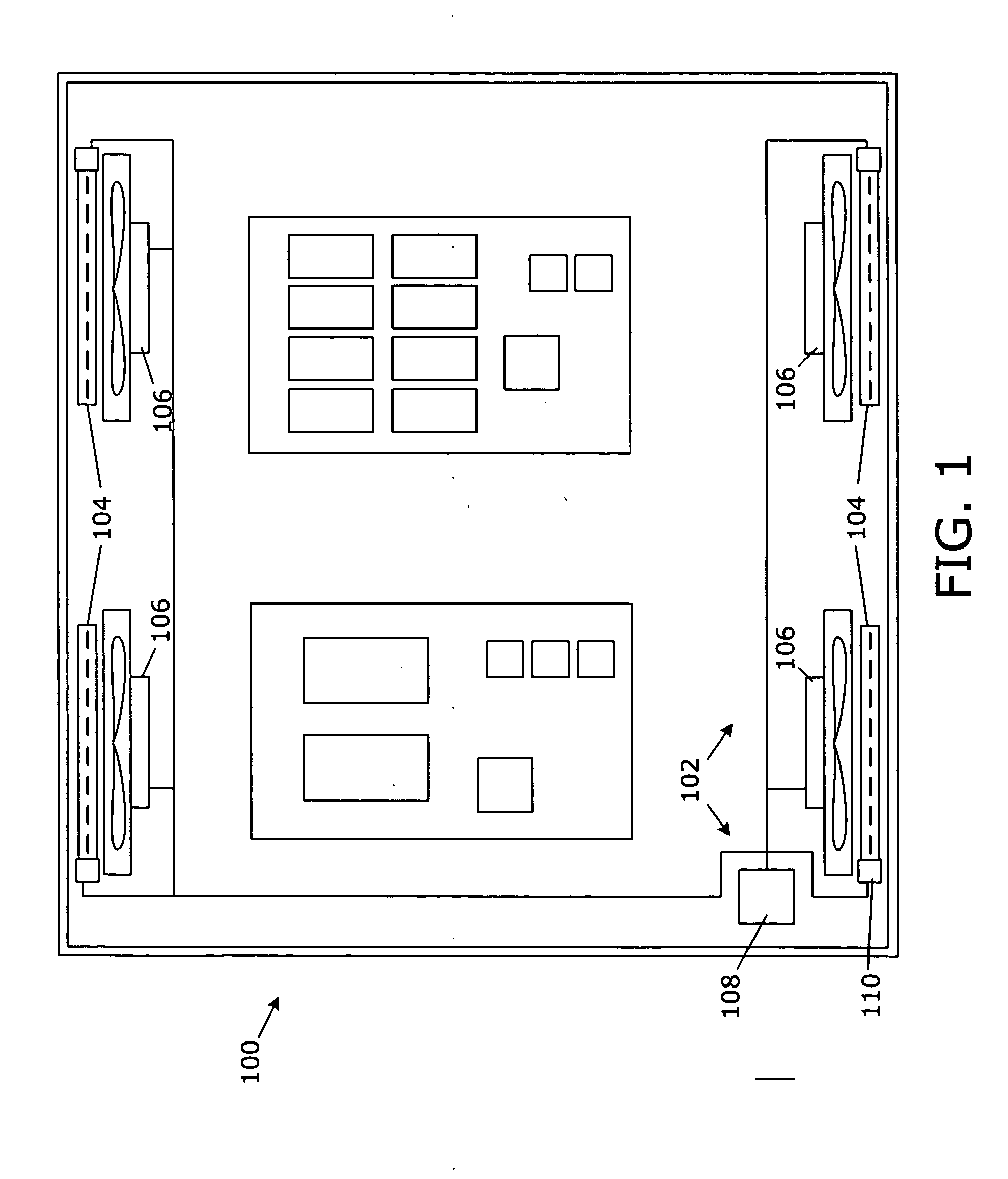
[0013] Referring to FIG. 1, a schematic pictorial and block diagram illustrates an overhead view of and embodiment of a cooling system 100 that includes an airflow control apparatus 102. The airflow control apparatus 102 further includes a controllable airflow resistance 104 aligned with an airflow path of a plurality of airflow paths, a sensor 106 capable of detecting an airflow condition in at least one of the plurality of airflow paths, and a controller 108. The controller 108 is coupled to the controllable airflow resistance 104 and to the sensor 106, and can control the controllable airflow resistance 104 to manage airflow recirculation based on the airflow condition detected by the sensor 106.

[0014] In various embodiments, the controllable airflow resistance 104 can be implemented as controllable louvers, sliding plates with variable perforations, variable sized vents or apertures, a perforated wall with associated sliding plates, shutters, and the like.

[0015] In some embodi...


PUM


Abstract

An airflow control apparatus includes a controllable airflow resistance aligned with an airflow path of a plurality of airflow paths, a sensor capable of detecting an airflow condition in at least one of the plurality of airflow paths, and a controller. The controller is coupled to the controllable airflow resistance and to the sensor, and can control the controllable airflow resistance to manage airflow recirculation based on the airflow condition detected by the sensor.

Description

BACKGROUND OF THE INVENTION [0001] Electronic systems and equipment such as computer systems, network interfaces, storage systems, and telecommunications equipment are commonly enclosed within a chassis, cabinet or housing for support, physical security, and efficient usage of space. Electronic equipment contained within the enclosure generates a significant amount of heat. Thermal damage may occur to the electronic equipment unless the heat is removed. [0002] Re-circulation of heated air can impact performance of electronic equipment. If airflow patterns allow re-usage of air that is previously heated by electronic equipment component to attempt to cool electronic equipment, less effective heat transfer from the equipment to the cooling airflow can result. In some circumstances insufficient heat transfer can take place and the equipment may overheat and potentially sustain thermal damage. [0003] One re-circulation scenario occurs when a fan fails and hot air exhausted from other ve...

Claims


Application Information

Patent Timeline
Patent Type & Authority Applications(United States)
IPC IPC(8): A61M16/00F24H3/06H05K7/20
CPCH05K7/20727F04D27/004H05K7/20836F04D25/14F04D25/166Y02B30/70
Inventor MALONE, CHRISTOPHER G.SIMON, GLENN C.
Owner HEWLETT-PACKARD ENTERPRISE DEV LP
Why Eureka
Try Eureka