Cutting element with improved cutter to blade transition

a cutting element and transition technology, applied in cutting machines, earth drilling and mining, construction, etc., can solve the problems of affecting the drilling budget, tripping out the borehole is a time-consuming and laborious endeavor, and all drill bit teeth can be expected to fail eventually, so as to improve the transition

Inactive Publication Date: 2005-11-03
SMITH INT INC
View PDF11 Cites 2 Cited by
  • Summary
  • Abstract
  • Description
  • Claims
  • Application Information

AI Technical Summary

Benefits of technology

[0015] In one embodiment, a slanted cutter configuration is disclosed, having a slanted top side that improves the transition between the cutter and the blade in which it is disposed.

Problems solved by technology

Tripping-out of the borehole is a time-consuming endeavor.
One trip can require days, and may significantly impact the drilling budget, as no drilling progress occurs during this period.
All drill bit teeth can be expected to fail eventually.
The first failure mode involves inward abrasive wear of the cutting face in which a side of the cutter's hardened face is gradually eroded inward, so that a portion of the tooth's volume is gradually removed.
A second failure mode involves fracture of the cutting face or the cutting teeth.
Because the force on the tooth's face is typically not evenly distributed, it is possible for failure in shear to occur (where part of the face, and possibly part of the body behind it, breaks away from the rest of the tooth).
This is a particularly damaging failure mode, as the separated tooth fragment is likely to be encountered by remaining cutting teeth.
There is also a chance of a cascading effect where shards from one or more broken teeth cause further tooth breakage which continues to propagate to other teeth of the bit.
With this type of failure, the single mass of hardened material has an even greater chance of damaging other teeth on the bit.
Although a greater volume of tooth embedded within the bit will reduce the likelihood of a prying out failure and results in an increased clearance, the bent tooth design is susceptible to increased fracture rates at the vertex of the bend.
Furthermore, the pockets and other tooth retention mechanisms are relatively complex compared to a typical straightforward cylindrical cutter design.
Additionally, because so much of a bent tooth is required to be embedded within the bit body, the number of teeth that may be located in a given area may be limited by the size of the bit body.
However, such partial enclosure of the top of the tooth may affect tooth clearance and the hemispherical back end may not permit as strong a braze as may be achieved with typical cylindrical cutter designs.

Method used


Image

  • Cutting element with improved cutter to blade transition
  • Cutting element with improved cutter to blade transition
  • Cutting element with improved cutter to blade transition

Examples


Embodiment Construction

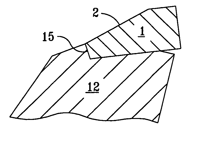
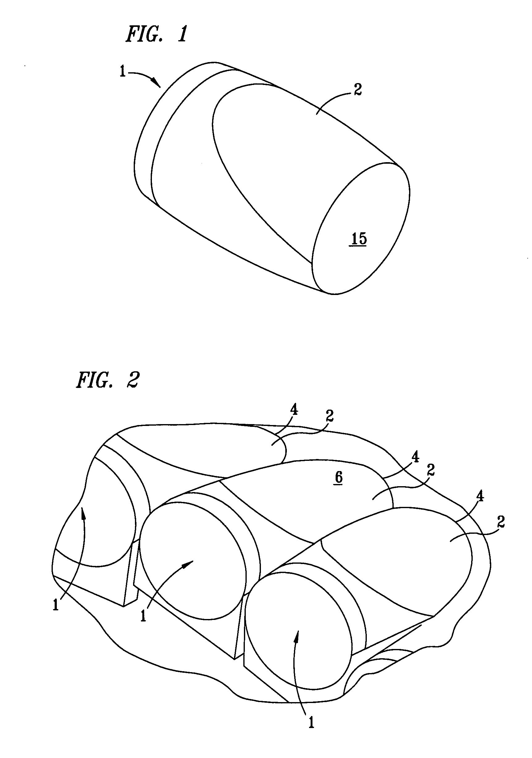
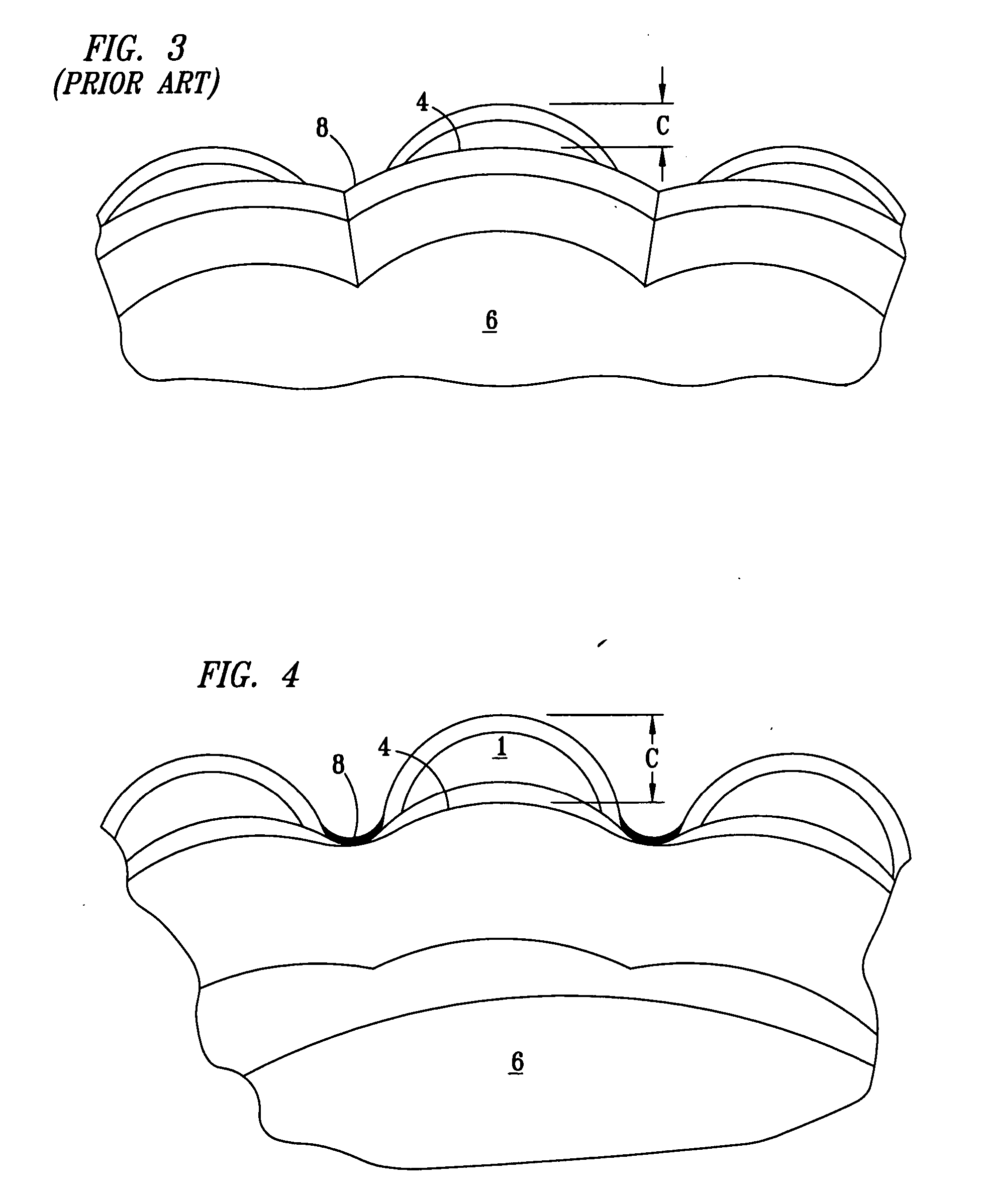
[0029]FIGS. 1 and 2 show improved cutter geometry according to an embodiment of the invention. This geometry maximizes cutter clearance and lessens the amount of formation contacting the bit body between the cutters. Less contact between the formation and bit body results in increased longevity for a drill bit. This is achieved by using a shape for a cutting element in which a generally cylindrical cutting element has a slanted top 2 for blending into the surrounding cutter blade 6. Such a configuration will be hereinafter referred to as a slanted cutter 1.

[0030] Top and bottom surfaces of cutters disclosed herein are defined with respect to the drill bit body in which they are or will be mounted, with the bottom surface being that which is closest to, or embedded in, the blade 6, and the top being that surface which is closest to a predicted location of the formation in which the drill bit is disposed. The back end 15 of the slanted cutter 1 will generally be disposed within a rec...


PUM

PropertyMeasurementUnit
angleaaaaaaaaaa
angleaaaaaaaaaa
angleaaaaaaaaaa

Abstract

Cutting elements having a slanted top surface for an improved cutter to blade transition, the slanted top surface being integratable into a receiving pocket of a bit blade such that the slanted top surface and the perimeter of the receiving pocket are relatively contiguous when the slanted cutter is mounted within the receiving pocket. Also, a bit with slanted cutters as well as a method of manufacturing a bit having slanted cutters.

Description

CROSS-REFERENCE TO RELATED APPLICATIONS [0001] The present invention claims the benefit of U.S. Provisional Patent Application No. 60 / 558,757 entitled “Cutting Element with Improved Cutter to Blade Transition,” filed on Apr. 1, 2004 by Peter Thomas Cariveau, hereby incorporated herein by reference.BACKGROUND OF THE INVENTION [0002] 1. Field of the Invention [0003] The invention relates generally to improvements in drag bit cutter geometries and the attachment of such cutters to a bit blade. [0004] 2. Background Art [0005] Oil wells and gas wells are typically created by a process of rotary drilling. In conventional rotary drilling a drill bit is mounted on the end of a drill string. At the surface a rotary drive turns the string, including the bit at the bottom of the hole, while a drilling fluid, or “mud,” is pumped through the drill string. [0006] When the bit wears out or breaks during drilling, it must be brought up out of the hole in a process called “tripping-out.” During this...

Claims


Application Information

Patent Timeline
Patent Type & Authority Applications(United States)
IPC IPC(8): B23P15/32E21B10/36E21B10/42E21B10/56E21B10/573
CPCE21B10/573E21B10/46
Inventor CARIVEAU, PETER THOMASWHITE, THOMAS B.
Owner SMITH INT INC
Why Eureka
Try Eureka