Torque converter for vehicle

Inactive Publication Date: 2005-11-03
KOREAN POWERTRAIN
View PDF9 Cites 27 Cited by
  • Summary
  • Abstract
  • Description
  • Claims
  • Application Information

AI Technical Summary

Benefits of technology

[0016] It is an objective of the present invention to provide a torque converter for a vehicle, which is designed to improve the torque converting efficiency and to be effectively

Problems solved by technology

When load applied to an engine is increased, the power transmission rate may be deteriorated.
Furthermore, since the lockup clutch is formed in a disk shape, when the disk-shaped clutch is subject to the hydraulic pressure, it may be deformed.
However, since retainer member must be attached on a shell of the turbine

Method used


Image

  • Torque converter for vehicle
  • Torque converter for vehicle
  • Torque converter for vehicle

Examples


Example

[0034] Reference will now be made in detail to the preferred embodiments of the present invention, examples of which are illustrated in the accompanying drawings. Wherever possible, the same reference numbers will be used throughout the drawings to refer to the same or like parts.

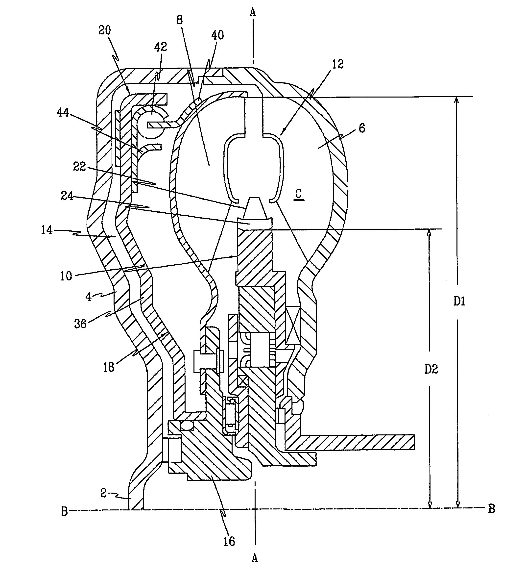
[0035]FIG. 1 is a half-sectional view of a torque converter according to an embodiment of the present invention, in which a left end of torque converter is connected to an engine and the torque converter has upper and lower halves that are identical to each other with reference to line C-C.

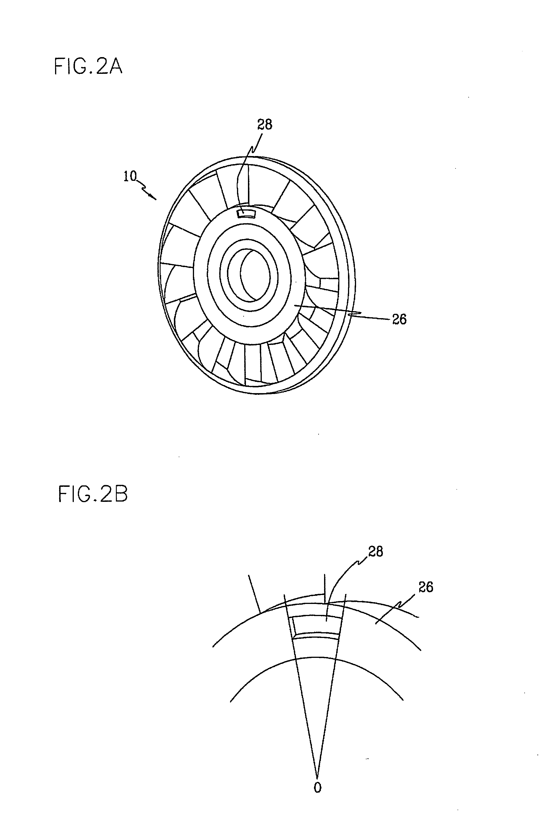
[0036] The inventive torque converter includes a front cover 4 integrally formed with a boss 2 to which a crank shaft of an engine side is connected, an impeller 6 connected to the front cover to rotate together, a turbine disposed facing the impeller 6, and a stator 10 disposed between the turbine 8 and the impeller 6 to cover the flow of oil directed from the turbine 8.

[0037] The impeller, turbine and stator 6, 8 and...


PUM


Abstract

A torque converter for a vehicle includes a front cover integrally formed with a boss to which a crank shaft of an engine side is connected, an impeller connected to the front cover to rotate together with the front cover, a turbine disposed facing the impeller, a stator disposed between the impeller and the turbine to convert flow of oil directed from the turbine, and a lockup clutch mechanism for directly connecting the engine to the turbine. The impeller, turbine, stator define a torque fluid actuating portion. An actuating chamber C has a ratio (D2/D1) of an inner diameter D2 to an outer diameter D1 is in a range of about 0.55-0.61.

Description

BACKGROUND OF THE INVENTION [0001] 1. Field of the Invention [0002] The present invention relates to a toque converter for a vehicle, and more particularly, to a torque converter for a vehicle, which is improved in the torque converting efficiency and degree of free design. [0003] 2. Description of the Related Art [0004] Generally, since a torque converter is designed to transmit power using fluid, it can control the speed acceleration and reduction. [0005] Such a torque converter includes an impeller rotating together with a torque shaft as a single body, a turbine rotating by oil pumped out from the impeller, and a stator improving the torque converting efficiency by directing the oil being returned to the impeller in a rotational direction of the impeller. [0006] Describing in more detail, the stator is designed to direct the oil, which is used to rotate the turbine, toward backsides of blades of the impeller, thereby boosting the rotation of the impeller. Accordingly, a shape of...

Claims


Application Information

Patent Timeline
IPC IPC(8): F16H41/26F16H45/02
CPCF16H41/26F16H2045/0294F16H2041/285F16H45/02
Inventor JOO, IN SIKJANG, JAE DUKKIM, DONG JINCHOI, WANLEE, JIN SOOPARK, EUN CHEOLLEE, HEON HO
Owner KOREAN POWERTRAIN
Why Eureka
Try Eureka