Plating apparatus and plating method

a plating apparatus and plating technology, applied in the direction of electrolysis process, semiconductor devices, electrolysis components, etc., can solve the problems of increased raw material costs, increased raw material cost, and longer plating time required

Inactive Publication Date: 2005-11-03
EBARA CORP +1
View PDF10 Cites 31 Cited by
  • Summary
  • Abstract
  • Description
  • Claims
  • Application Information

AI Technical Summary

Benefits of technology

[0012] As described above, the plating solution containing metal ions, a supporting electrolyte, halogen ions, and at least one of an organic sulfur compound, a high polymer compound, and an organic nitrogen compound is employed, and the process of holding the conductive layer and the porous member in contact with each other and moving the conductive layer and the porous member relatively to each other without passing an electric current between the conductive layer and the anode, and the process of passing an electric current between the conductive layer and the anode while keeping the conductive layer still with respect to the porous member, and the process of stopping the supply of the electric current between the conductive layer and the anode, are repeated to embed metal in the fine interconnect recesses. It has been confirmed that according to the above method, it is possible to preferentially deposit a plated film in fine interconnect recesses such as trenches and via holes, and deposit the plated film to a flatter surface without being affected by variations of the shape (widths or sizes differences) of the trenches, or the via holes, or the like.
[0013] In a preferred embodiment of the present invention, the metal ions comprise copper ions, and the copper ions in the plating solution has a concentration ranging from 30 to 60 g / L. This makes it possible to form interconnects made of copper that is highly electrically conductive (copper interconnects).

Problems solved by technology

However, in the prior art, when plating is performed, an amount of plated material is different in regions of the surface of the substrate depending on the shape variations (widths or sizes differences) of the interconnect pattern, such as trenches and via holes, under the influence of distribution of current density or the influence of additives, and hence it is difficult to form a plated film having a uniform thickness over the entire surface of the substrate.
As a result, in a case where an interconnect pattern is filled entirely with interconnect material such as copper by plating, the thickness of a plated film differs depending on the locations, causing irregularities in the plated film surface.
When plating is performed according to such method, more amount of plated material than necessary is deposited, and hence raw material cost increases and a longer period of plating time is required.
These ideas or attempts can achieve the object to a certain extent but have a limitation such as a plated film of poor quality.

Method used


Image

  • Plating apparatus and plating method
  • Plating apparatus and plating method
  • Plating apparatus and plating method

Examples


example 1

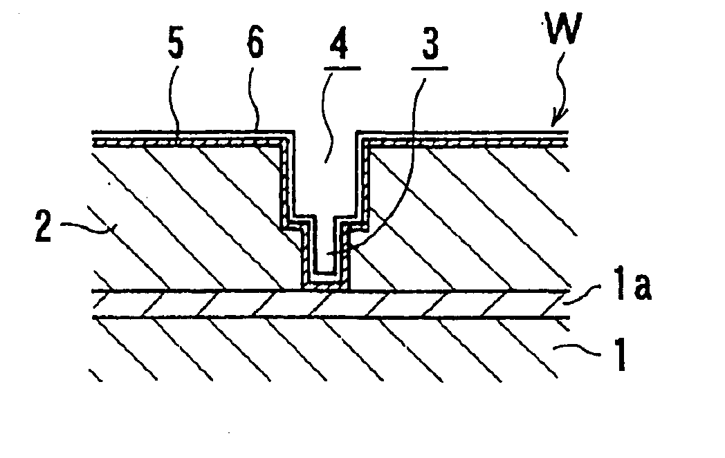
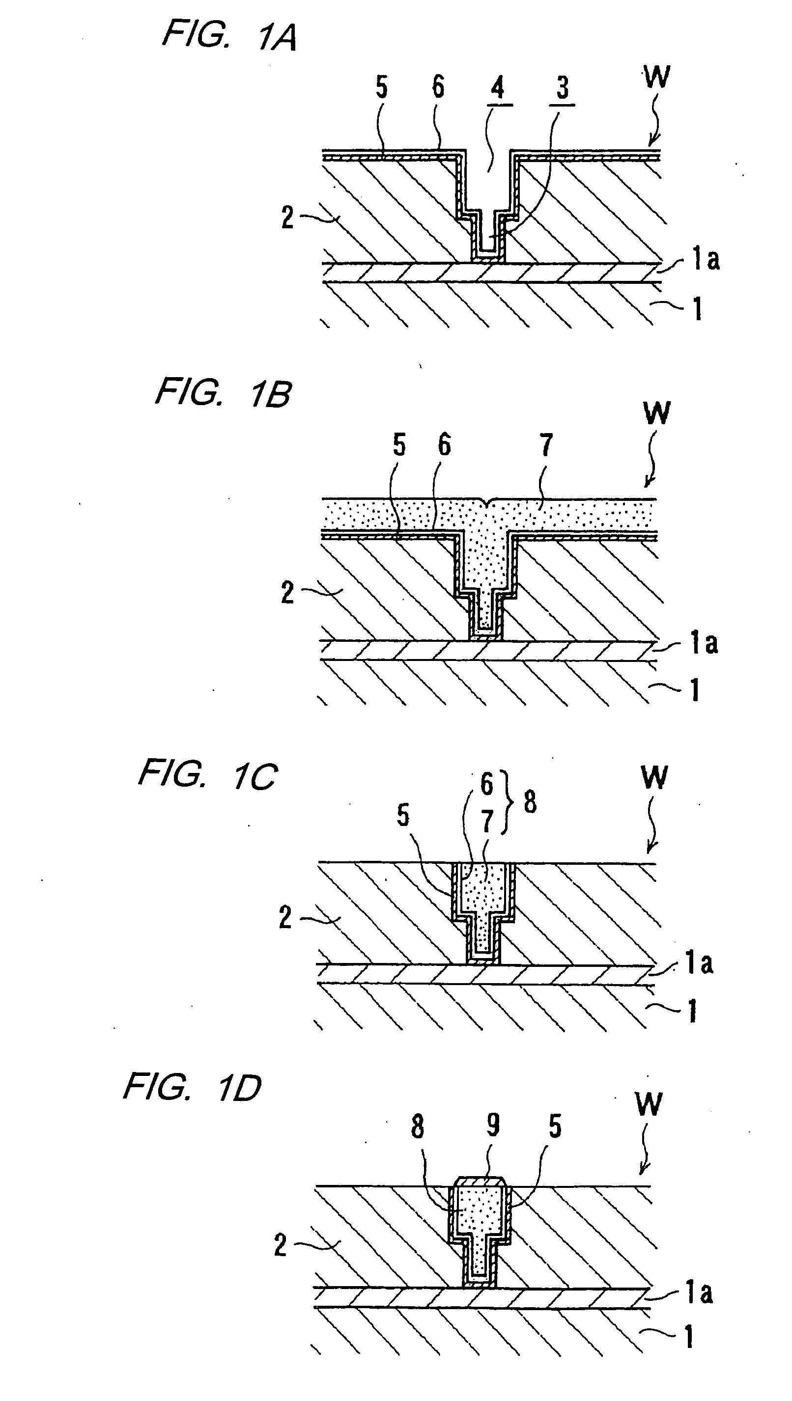
[0168] As shown in FIG. 28, a number of fine interconnect trenches 40 each having a width of 0.18 μm and a depth of 1.0 μm at close intervals of 0.18 μm, and a single wider interconnect trench 42 having a width of 20 μm and a depth of 1.0 μm are formed in a silicon wafer 44 having a diameter of 200 mm. After a barrier layer is deposited on the surface of the silicon wafer 44 by PVD, a copper seed layer as a conductive layer is deposited to a thickness of 80 nm on the barrier layer by PVD to prepare a sample.

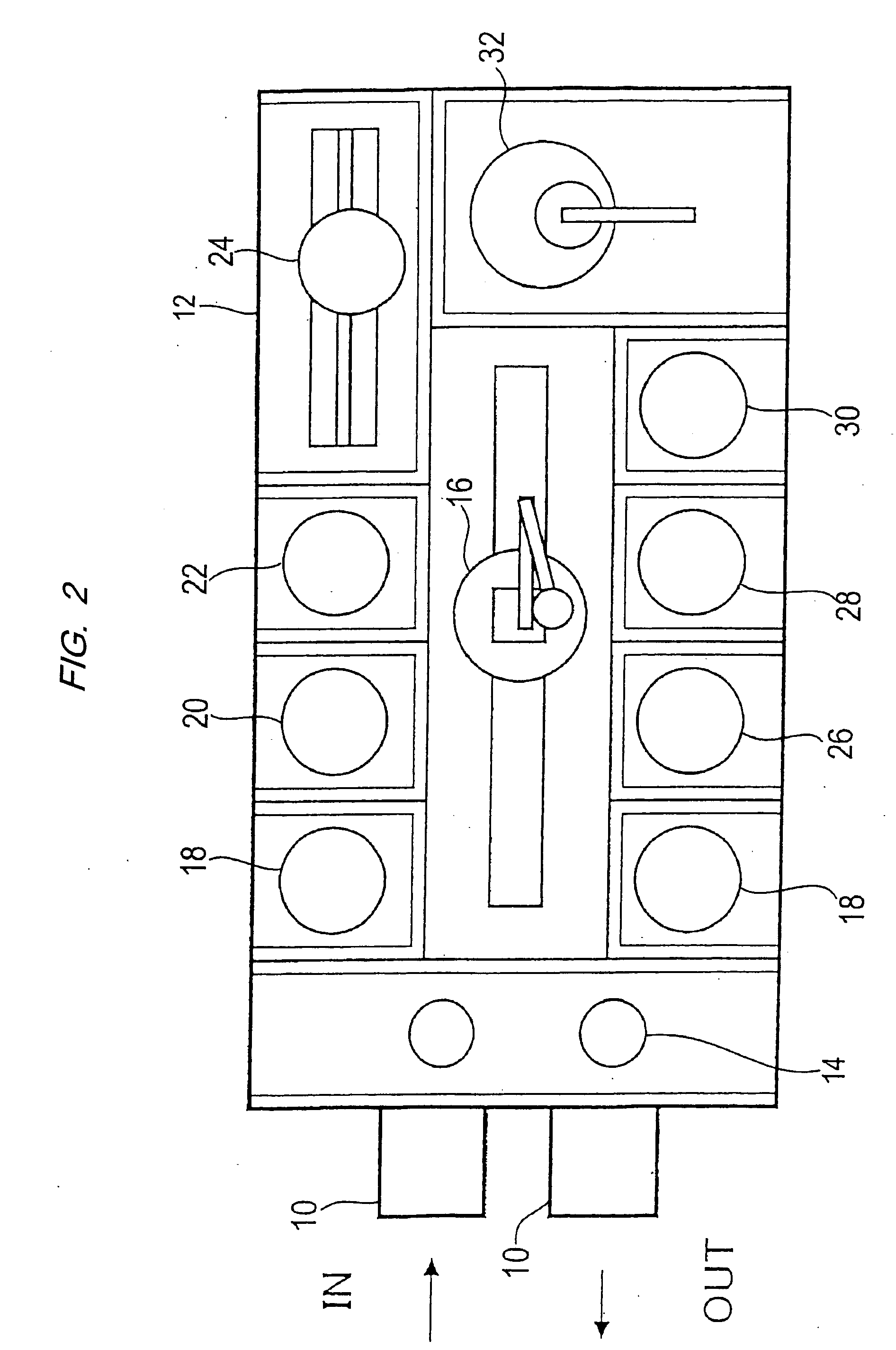
[0169] Using a copper sulfate plating solution having the composition described below, the surface of the sample was subjected to electroplating by a plating apparatus which is essentially the same structure as the plating apparatus shown in FIG. 3 to deposit a copper plated film 46 having a thickness of about 500 nm on the surface of the copper seed layer. [0170] Copper sulfate 5-hydrate: 200 g / L [0171] Sulfuric acid: 50 g / L [0172] Chloride: 60 mg / L [0173] Sulfur compound (N,N-...

example 2

[0178] Using the same sample as with Example 1 and under the same plating conditions as with Example 1, the surface of the sample was subjected to electroplating to deposit a plated copper film 46 (see FIG. 28) having a thickness of about 500 nm on the surface of the copper seed layer. However, the plating solution used contained 150 mg / L of polyoxypropylenetriol (molecular weight=300), rather than polypropylene glycol used in Example 1, as the high polymer compound. The deposited plated copper film 46 was evaluated in terms of the flatness index and the surface step as with Example 1.

example 3

[0179] Using the same sample as with Example 1 and the plating solution having the same composition as with Example 1, the surface of the sample was subjected to electroplating to deposit a plated copper film 46 (see FIG. 28) having a thickness of about 500 nm on the surface of the copper seed layer. The plating conditions were as follows: The copper seed layer on the sample and the lower pad (porous member) 534a were brought into contact with each other, and the lower pad 534a was vibrated for 3 seconds. After the vibration of the lower pad 534a was stopped, an electric current at a current density of 10 mA / cm2 was passed between the copper seed layer on the sample and the anode 526 for 10 seconds. After the supply of the electric current between the copper seed layer on the sample and the anode 526 was stopped, the lower pad 534a was released from the copper seed layer on the sample, and the electrode head 502 was left to stand for 2 to 3 seconds. The above process beginning with ...


PUM

PropertyMeasurementUnit
concentrationaaaaaaaaaa

Abstract

A plating method is capable of mechanically and electrochemically preferentially depositing a plated film in fine interconnect recesses such as trenches and via holes, and depositing the plated film to a flatter surface. The plating method including: disposing a substrate having fine interconnect recesses such that a conductive layer faces an anode; disposing a porous member between the substrate and the anode; filling a plating solution between the substrate and the anode; and repeating a process of holding the conductive layer and the porous member in contact with each other and moving the conductive layer and the porous member relatively to each other, a process of passing an electric current between the conductive layer and the anode while keeping the conductive layer still with respect to the porous member, and a process of stopping the supply of the electric current between the conductive layer and the anode.

Description

BACKGROUND OF THE INVENTION [0001] 1. Field of the Invention [0002] The present invention relates to a plating apparatus and a plating method, and more particularly to a plating apparatus and a plating method used for filling a fine circuit pattern formed in a substrate, such as a semiconductor substrate, with metal (interconnect material) such as copper so as to form interconnects. [0003] 2. Description of the Related Art [0004] Recently, there has been employed a circuit forming method comprising forming fine recesses for interconnects, such as trenches or via holes in a circuit form, in a semiconductor substrate, embedding the fine recesses with copper (interconnect material) by copper plating, and removing a copper layer (plated film) at portions other than the fine recesses by CMP or the like. In this damascene method, from the viewpoint of reducing loads on subsequent CMP, it is desirable that a copper plated film be deposited selectively in trenches or via holes in a circuit ...

Claims


Application Information

Patent Timeline
Patent Type & Authority Applications(United States)
IPC IPC(8): C25D3/38C25D5/00C25D5/02C25D5/08C25D5/18C25D7/12C25D17/00H01L21/288H01L21/768
CPCC25D3/38C25D5/02C25D5/18H01L21/2885C25D17/007C25D17/008C25D7/123C25D17/001H01L21/76877C25D5/611C25D5/625
Inventor NAGAI, MIZUKIKANDA, HIROYUKIKURASHINA, KEIICHIYAMAMOTO, SATORUKIMIZUKA, RYOICHIDELIGIANNI, HARIKLIABAKER, BRETTKWIETNIAK, KEITHANDRICACOS, PANAYOTISVEREECKEN, PHILIPPE
Owner EBARA CORP
Why Eureka
Try Eureka