Multi-color solid state light emitting device

a light emitting device and solid state technology, applied in the direction of semiconductor devices for light sources, discharge tubes luminescnet screens, lighting and heating apparatus, etc., can solve the problems of high voltage and high energy devices, inconsistent life patterns, and installation and replacement of licensed tradesmen, etc., to achieve low voltage and energy efficiency, long life, and chromatically versatile

Inactive Publication Date: 2005-11-03
BLOOMFIELD JOSEPH +2
View PDF6 Cites 59 Cited by
  • Summary
  • Abstract
  • Description
  • Claims
  • Application Information

AI Technical Summary

Benefits of technology

[0011] A second object of the invention is to provide a light emitting device that is durable, low voltage and energy efficient.
[0012] A third object of the invention is to provide a light emitting device that is chromatically versatile and continues to glow when electrical power is removed.
[0013] A fourth object of the invention is to provide a light emitting device that has a long life, and is easy to install and maintain.

Problems solved by technology

They are fragile, high voltage, and high energy devices.
In addition, they have inconsistent life patterns and require licensed tradesmen for installation and replacement.
However, Slayden does not use fluorescent and phosphorescent pigment in the diffuser.

Method used


Image

  • Multi-color solid state light emitting device
  • Multi-color solid state light emitting device
  • Multi-color solid state light emitting device

Examples


Embodiment Construction

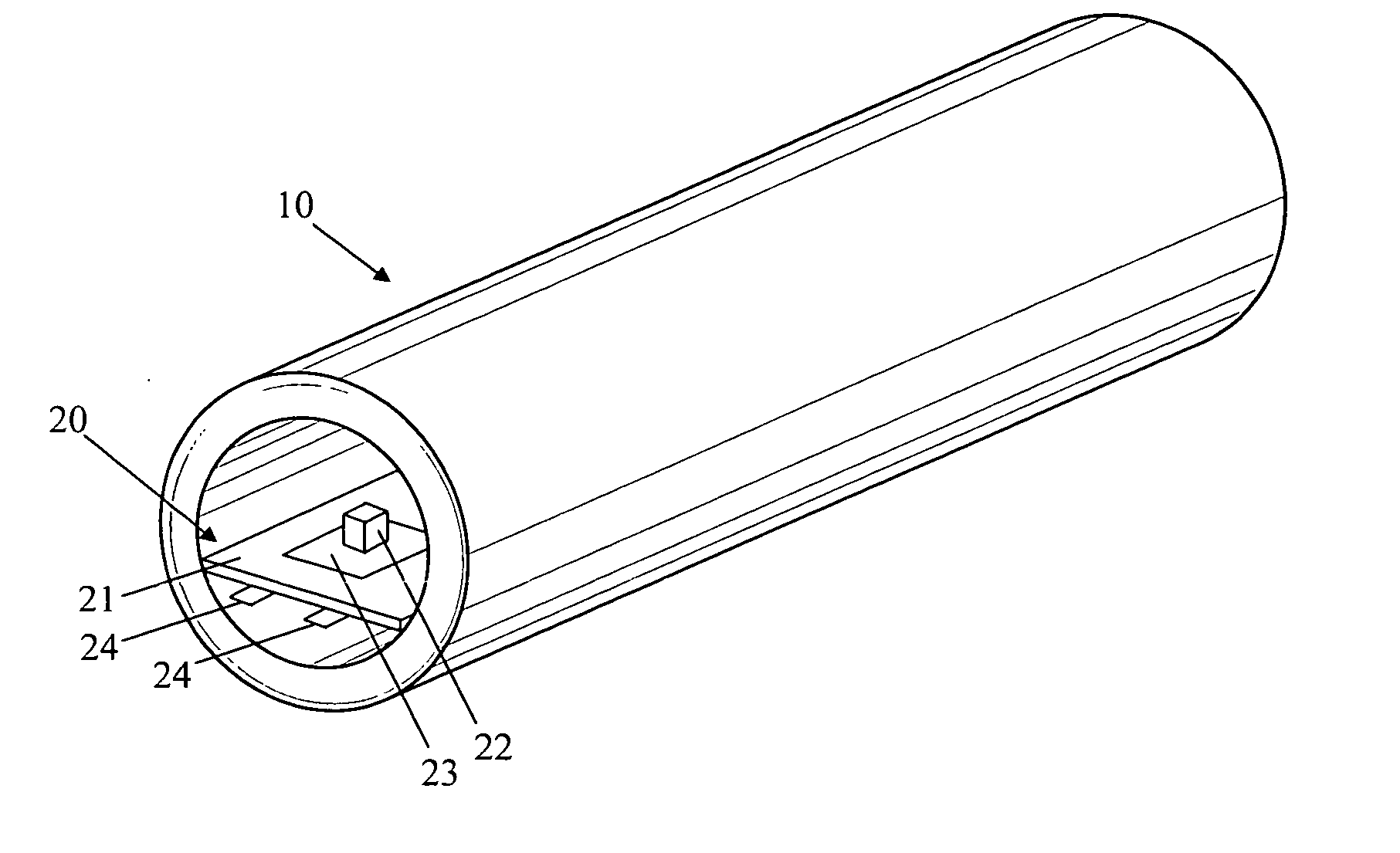
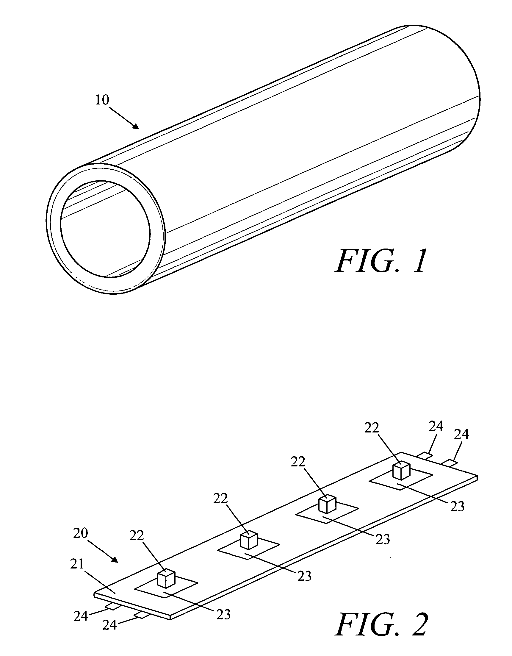
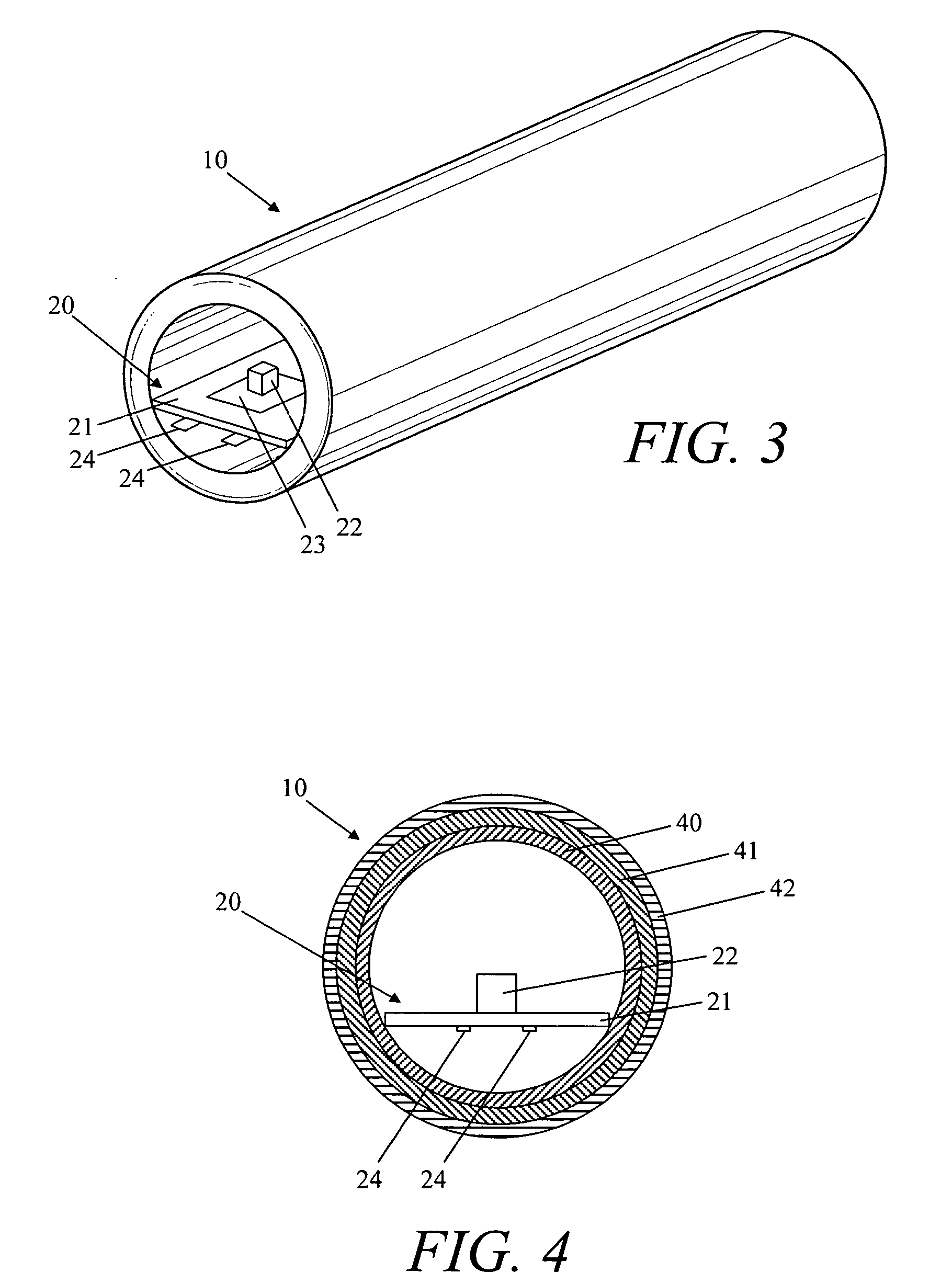
[0021] Referring now to FIG. 1, a perspective view of a tube used in accordance with the present invention is shown. Tube 10 is comprised of a clear carrier mix such as plastic or another similar material. The cross-section of tube 10 can be formed in different shapes, including round, oval, square, rectangle, hexagon and octagon. Tube 10 can also assume different shapes longitudinally, for example, to spell a word. Tube 10 has fluorescent and phosphorescent pigments embedded within it.

[0022] Fluorescent pigment is a material made from metallic oxide with rare earth additives. Fluorescent pigment has the property of absorbing ultra-violet light of 360 nm wavelength and immediately emitting visible light. Fluorescent pigment comes in many colors. The pigment can be cast molded, ejection molded, or extrusion molded with different pigment volume to achieve different colors and intensities of color.

[0023] Phosphorescent pigment is a powder that continues to radiate visible light after...


PUM

PropertyMeasurementUnit
wavelengthaaaaaaaaaa
projection angleaaaaaaaaaa

Abstract

A light emitting device for simulating neon light and method for doing the same. The light emitting device includes an elongated container having a combination of fluorescent pigment and phosphorescent pigment embedded therein. The light emitting device further includes a plurality of light emitting diodes aligned within the container. Finally, the light emitting device includes electrical means for providing electricity to the plurality of diodes.

Description

BACKGROUND OF THE INVENTION [0001] 1. Field of the Invention [0002] The invention relates in general to lighting equipment. More particularly, this invention relates to a device and method that combine light emitting diodes (LEDs) with fluorescent and phosphorescent pigment to simulate neon light. [0003] 2. Description of the Related Art [0004] Neon lights have been used for numerous years. They are made of long, narrow glass tubes and come in a variety of shapes. The tube of a neon light can spell out a word, for example. [0005] Inside the glass tube of a neon light, there is a gas such as neon, argon or krypton at low pressure. Both ends of the tube have metal electrodes. When a high voltage is applied to the electrodes, the neon gas ionizes, and electrons flow through the gas. These electrons excite the neon atoms and cause them to emit visible light. Neon emits red light when energized in this way. Other gases emit colors such as blue, green, yellow and white when energized. [00...

Claims


Application Information

Patent Timeline
Patent Type & Authority Applications(United States)
IPC IPC(8): F21K99/00F21S4/00H05B33/00
CPCF21K9/00F21Y2101/02F21S4/003F21S4/20F21Y2103/10F21Y2115/10F21V3/062F21V3/08F21V9/38
Inventor BLOOMFIELD, JOSEPH
Owner BLOOMFIELD JOSEPH
Why Eureka
Try Eureka