Battery receiving device, power source device using the same, and electric motor vehicle using the devices

a power source device and battery technology, applied in secondary cells, battery service/maintenance, cell components, etc., can solve the problems of sealing mechanism breakage, inconvenience in the safety of characteristic and reliability, and dissipation of organic electrolyte from a safety valve, so as to improve the vehicle characteristic and safety

Inactive Publication Date: 2005-11-03
PANASONIC CORP
View PDF7 Cites 30 Cited by
  • Summary
  • Abstract
  • Description
  • Claims
  • Application Information

AI Technical Summary

Benefits of technology

[0047] The electric vehicle having such a structure is adaptable to widespread temperatu

Problems solved by technology

While, the characteristic of a secondary battery and the reliability including the lifetime and safety largely depend on the battery and its environmental temperature, and affect the characteristic and reliability of the vehicle to which the battery is mounted.
When the lithium secondary battery is used or left for a long time at a higher ambient temperature of 60° C., the organic electrolyte from a safety valve dissipates, or the sealing mechanism breaks.
These phenomena cause inconvenience in safety of the characteristic and reliability.
A conventional cooling mechanism such as a compressor has a complex mechanism and requires much energy.
However, practical application to a high temperature environment is kept at a distance, and the general purpose property is apt to be restricted.
When the electric automobile is required to be applicable to widespread temperature environment and quality

Method used


Image

  • Battery receiving device, power source device using the same, and electric motor vehicle using the devices
  • Battery receiving device, power source device using the same, and electric motor vehicle using the devices
  • Battery receiving device, power source device using the same, and electric motor vehicle using the devices

Examples


exemplary embodiment 1

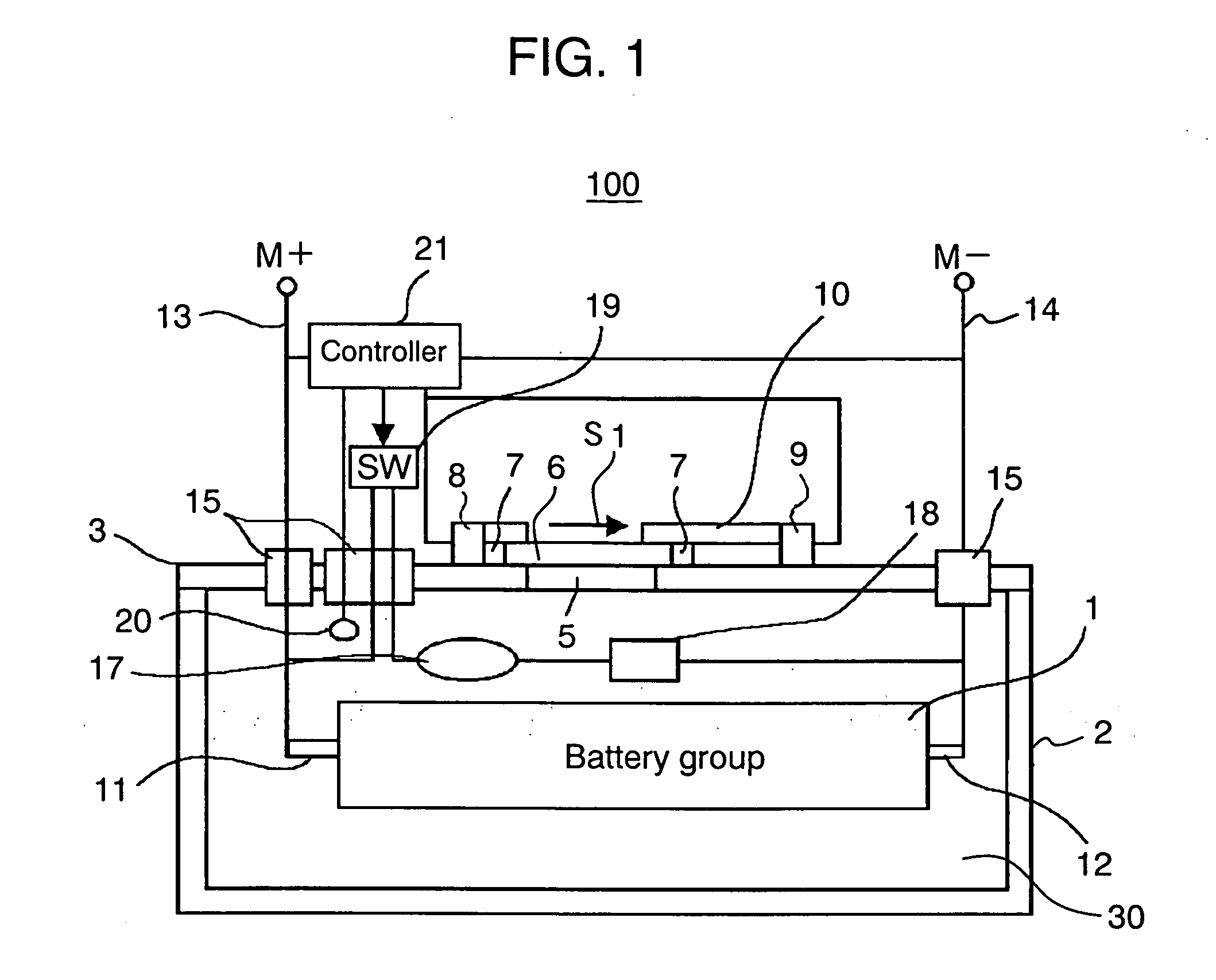
[0056] (Exemplary Embodiment 1)

[0057]FIG. 1 is a diagram of a battery storing device in accordance with exemplary embodiment 1 of the present invention. Battery storing device 100 has battery storing box body 2 capable of storing battery group 1 inside and lid body 3 of battery storing box body 2. Magnetic materials 7 are disposed at ends of opening / closing lid body 6. Battery storing device 100 has the following elements: [0058] electromagnets 8 and 9 for opening and closing opening / closing lid body 6 in the direction indicated by code S1; [0059] guide 10 for opening, closing, or moving opening / closing lid body 6; [0060] PTC device 17; and [0061] resistance device 18 such as a nichrome wire that is a normal heating resistor. Battery storing device 100 also has switch 19, temperature detector 20, and controller 21 for controlling opening and closing of opening / closing lid body 6, PTC device 17, and resistance device 18.

[0062] Battery storing box body 2, lid body 3, and opening / clos...

exemplary embodiment 2

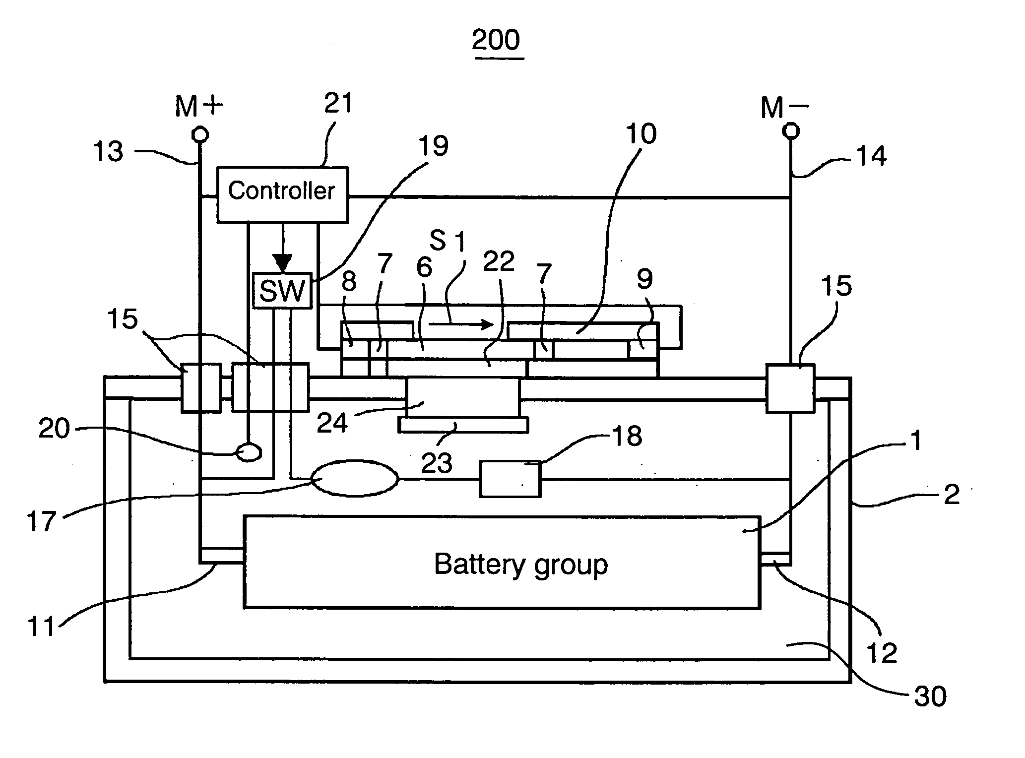
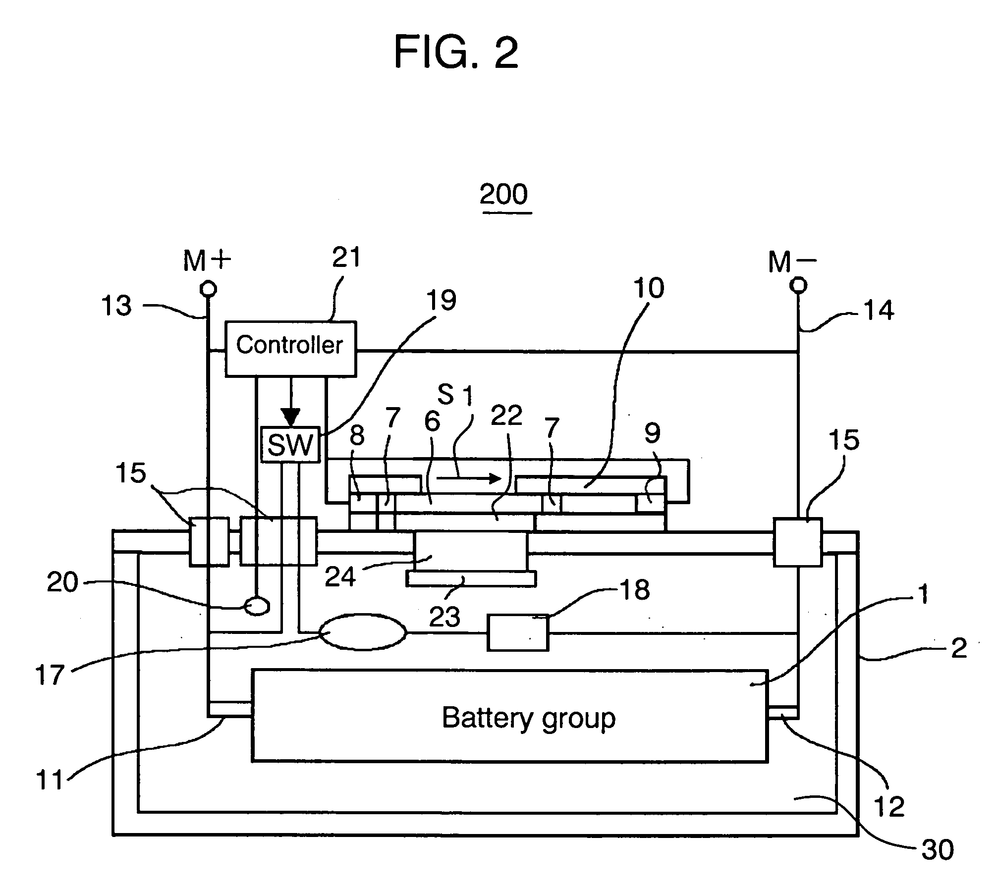
[0092] (Exemplary Embodiment 2)

[0093]FIG. 2 is a diagram of battery storing device 200 in accordance with exemplary embodiment 2 of the present invention. Battery storing device 200 has a heat-retention releasing mechanism different from that of exemplary embodiment 1.

[0094] In FIG. 2, battery storing device 200 has the following elements: [0095] battery storing box body 2 capable of storing battery group 1 inside; [0096] lid body 3; [0097] opening / closing lid body 6; [0098] electromagnets 8 and 9; [0099] guide 10; [0100] PTC device 17; [0101] resistance device 18; [0102] switch 19; [0103] temperature detector 20; [0104] controller 21; [0105] fins 22 and 23 for heat dissipation or heat collection; and [0106] heat conduction body 24 for conducting heat between fins 22 and 23.

Here, configurations except fins 22 and 23 and heat conduction body 24 are the same as those of exemplary embodiment 1, and the description of the configurations is omitted.

[0107] Fins 22 and 23 and heat cond...


PUM


Abstract

The present invention provides battery storing device (100) that can easily suppress temperature increase in a battery and a battery storing section in high-temperature using environment, without damaging excellent heat retaining function of the battery that is required for low-temperature using environment. Battery storing device (100) has battery storing box body (2), battery storing section (30) in the box body, and battery group (1) stored in battery storing section (30). Battery storing box body (2) is made of heat insulating material and has a heat retaining function of battery group (1). Battery storing device (100) further has lid body (3), opening/closing lid body (6) for opening and closing opening (5) for releasing the heat retaining function, magnetic material (7) disposed at an end of opening/closing lid body (6), electromagnet (8), and electromagnet (9).

Description

TECHNICAL FIELD [0001] The present invention relates to a battery storing device capable of storing a battery inside, a power supply device using it, and an electric vehicle using them. Especially, the present invention relates to a battery storing device and power supply device appropriate to use a battery in widespread environment from high temperature to low temperature in an electric automobile or the like. BACKGROUND ART [0002] Recently, for addressing environmental issues and energy problems, an automobile that uses output from a secondary battery as the driving source and at least partially has an electrically driven device has received attention. [0003] Such an electric automobile uses output from the secondary battery as the entire driving source, and is run by driving force of a motor. A so-called hybrid car system that concurrently uses a motor and an engine and a so-called idle stop system car proceed toward commercialization in some manufacturer. Here, the so-called idl...

Claims


Application Information

Patent Timeline
IPC IPC(8): H01M10/44B60L3/00H01M10/60H01M10/613H01M10/615H01M10/625H01M10/6551H01M10/6563H01M10/6571H01M10/658H01M50/202H02J7/04
CPCH01M2/1072H01M2/1094H01M10/052H01M10/5006Y02T10/7011H01M10/5083H01M10/5087H01M2200/106H01M10/5016H01M10/625H01M10/615H01M10/6571H01M10/658Y02E60/10H01M50/24H01M50/202
Inventor KADOUCHI, EIJIKIMURA, KENJI
Owner PANASONIC CORP
Why Eureka
Try Eureka