Angular speed detecting device

a technology of angular speed and detection device, which is applied in the direction of galvano-magnetic hall effect devices, digital computer details, instruments, etc., can solve problems such as difficulty, and achieve the effect of improving angular speed detecting and accurately detecting angular speed

Inactive Publication Date: 2005-11-03
DENSO CORP
View PDF1 Cites 23 Cited by
  • Summary
  • Abstract
  • Description
  • Claims
  • Application Information

AI Technical Summary

Benefits of technology

[0006] Therefore, it is an object of the invention to provide an improved angular speed detecting device that can accurately detect angular speed irrespective of the angular position.

Problems solved by technology

However, when one intends to obtain the angular speed of the rotating object from the rotation angle around 360 degrees from the output angle θ, he will have a difficulty because the output angle θ before or after 360 degrees changes too sharply to differentiate it, as shown in FIG. 19.

Method used


Image

  • Angular speed detecting device
  • Angular speed detecting device
  • Angular speed detecting device

Examples


first embodiment

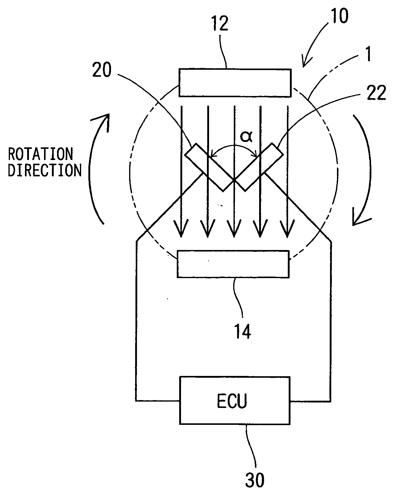
[0031] An angular speed detecting device 10 according to the invention to be used for detecting the angular speed of a rotating object 1, such as a crankshaft or a vehicle wheel, will be described with reference to FIGS. 1-5, 16 and 17. The angular speed detecting device 10 includes a pair of permanent magnets 12 and 14, a pair of hall elements 20 and 22 and an electronic control unit (hereinafter referred to as the ECU) 30.

[0032] The permanent magnets 12, 14 provide a generally even magnetic field or a constant magnetic flux density in the space between them. The pair of hall elements 20, 22 have the same construction and disposed in the space between the permanent magnets 12, 14 to incline to each other at an angle α (e.g. 90 degrees) and to the magnetic field at half the angle α . Therefore, when the rotating object 1 rotates and the hall elements are electrically powered, the hall elements 20 generates a sinusoidal voltage signal Va and the hall element 22 generates a sinusoidal...

second embodiment

[0041] An angular speed detecting device 10 according to the invention will be described with reference to FIGS. 6-8. The angular speed detecting device 10 is substantially the same in construction except for the processing program for obtaining the angular speed of the rotation object 1, which is installed into the ECU 30.

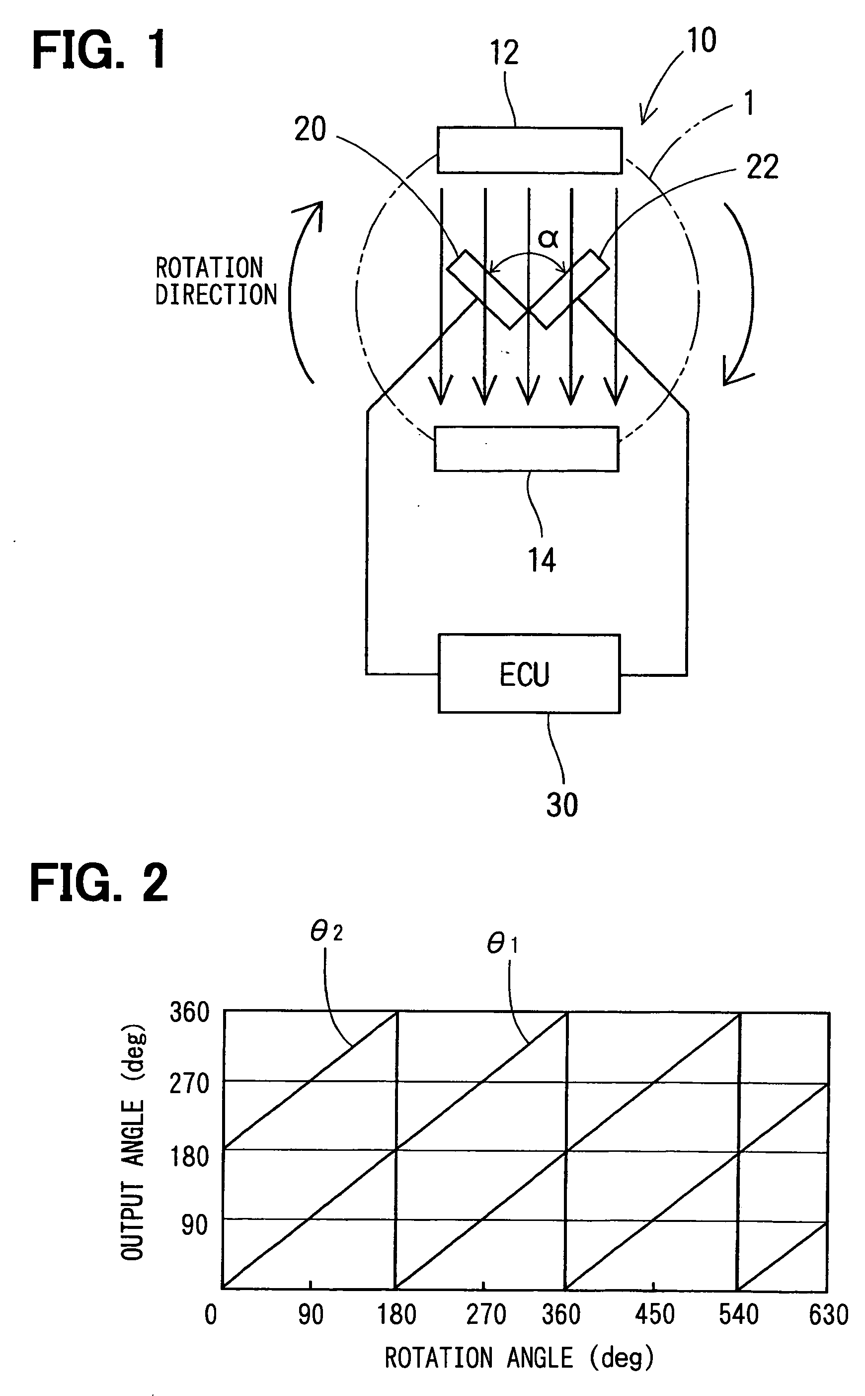
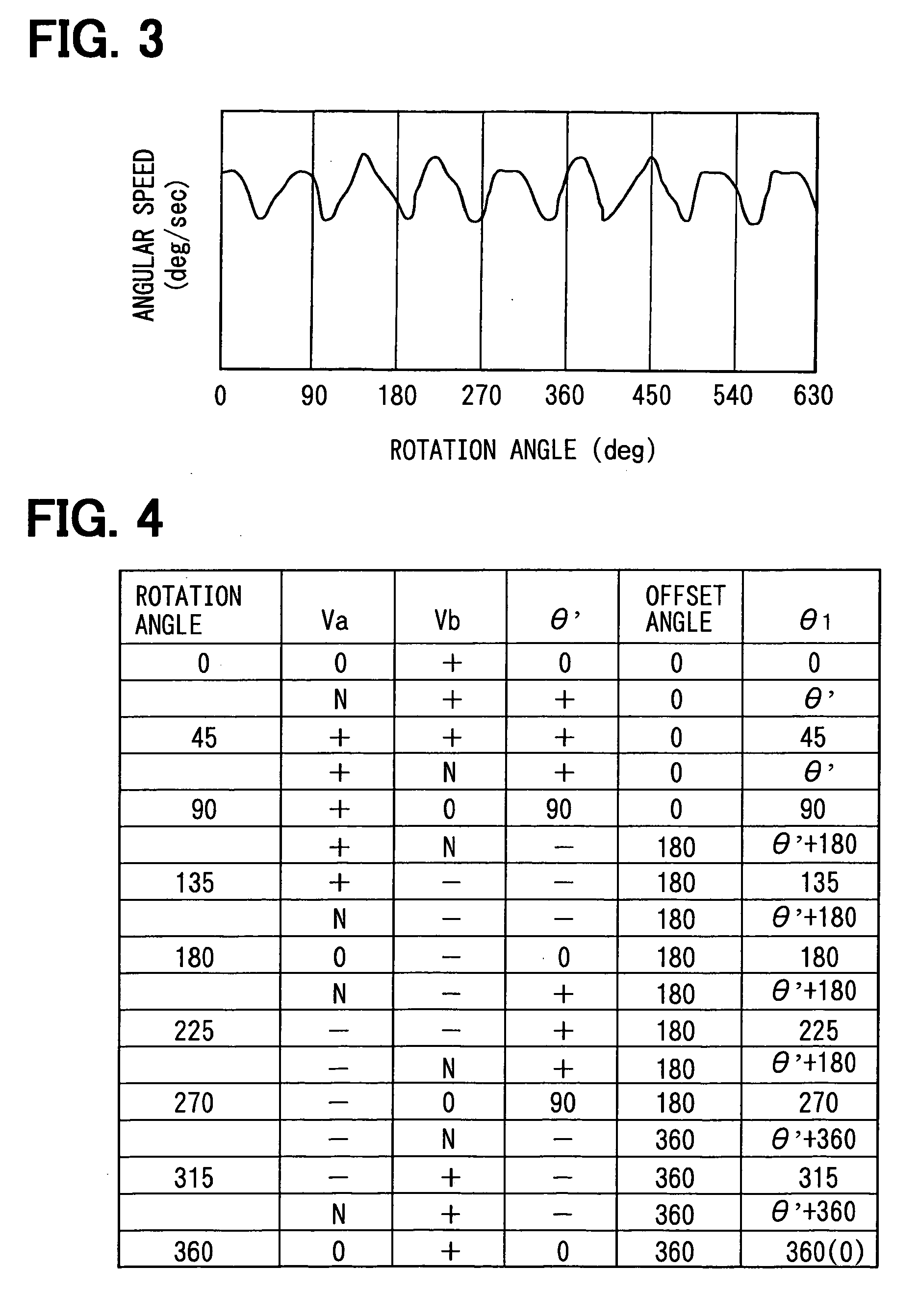
[0042] The ECU 30 provides a pair of saw-tooth-wave curves of output angles θ1 and θ2 by adding offset angles to the trigonometric value θ′, as shown in FIGS. 7 and 8, in which character N indicates that the plus or minus sign is neglected to distinguish the angular position. In this case, plus and minus sign of the sum (i.e. Va+Vb) and difference (i.e. Va−Vb) of the voltage signals Va and Vb are used to distinguish the angular position of the rotating object instead of the plus and minus sign of each of the voltage signals Va, Vb. The sum and the difference can be expressed as follows:

Va+Vb=kBI·sin θ+kBI·cos θ={square root}{square root over (2)}kBI·sin (θ+45)   ...

third embodiment

[0045] An angular speed detecting device 40 according to the invention will be described with reference to FIG. 9.

[0046] The angular speed detecting device 40 includes a pair of permanent magnets 12 and 14, three hall elements 20, 22 and 24 and the ECU 30.

[0047] The hall elements 20, 22, 24 have the same construction and disposed in the space between the permanent magnets 12, 14 to incline to each other at an angle of 90 degrees. Therefore, when the rotating object 1 rotates and the hall elements are electrically powered, the hall elements 20, 22 and 24 generates sinusoidal voltage signals that are 90 degrees in electric angle different from another. In other words, the hall element 20 generates a sinusoidal voltage signal Va, the hall element 22 generates a sinusoidal voltage signal Vb, and the hall element 24 generates a sinusoidal voltage signal Vc, as shown in FIG. 10.

[0048] The ECU 30 calculates, using the expression (5) and (6), a trigonometric value θ0′ from the voltage sig...


PUM


Abstract

An angular speed detecting device is composed of a magnetic sensor unit connected to a rotating object and including a permanent magnet and a pair of magnetic sensor elements to generate a pair of signals and an electric computing unit that calculates an angular speed from the signals. The electric computing unit calculates the angular speed by the following steps: forming sine and cosine functions of an angle θ′ from the signals; forming a saw-tooth curve of the angle θ′; forming a table showing plus or minus sign of the signals and the saw-tooth curve of the angle θ′ at a plurality of rotation angles of the rotating object; forming a pair of curves of output angles θ1 and θ2 in terms of 360-degree angular range by distinguishing rotation position of the rotating object from a combination of the plus, or minus sign of the signals and the saw-tooth curve of the angle θ′; and selectively using curves of the output angles θ1 and θ2 to calculate the angular speed of a rotating object.

Description

CROSS REFERENCE TO RELATED APPLICATION [0001] The present application is based on and claims priority from Japanese Patent Application 2004-135252, filed Apr. 30, 2004, the contents of which are incorporated herein by reference. BACKGROUND OF THE INVENTION [0002] 1. Field of the Invention [0003] The present invention relates to an angular speed detecting device that detects the rotation speed of a rotating object. [0004] 2. Description of the Related Art [0005] A magnetic sensor unit that is composed of a pair of magnetic sensing elements and a magnetic field setting member is well-known for a device to detect the rotation angle of a rotating object, as disclosed in JP-A-2002-340511. In such a device, a pair of sensor elements provides signals Va and Vb, as shown in FIG. 16. Then, a saw-tooth-wave curve of trigonometric values θ′ that correspond to the arctangent of the signals Va and Vb, is provided as shown in FIG. 17. Then, plural rotation angle ranges of the rotating object betw...

Claims


Application Information

Patent Timeline
Patent Type & Authority Applications(United States)
IPC IPC(8): G01P3/44G01D5/14G01P3/48G01P3/487G01P3/54
CPCG01D5/145G01P3/487G01P3/48
Inventor MATSUMOTO, KOICHIROKITANAKA, TATSUYA
Owner DENSO CORP
Why Eureka
Try Eureka