Detection of ferromagnetic objects approaching a magnet

Inactive Publication Date: 2005-11-03
NAT RES COUNCIL OF CANADA
View PDF8 Cites 39 Cited by
  • Summary
  • Abstract
  • Description
  • Claims
  • Application Information

AI Technical Summary

Benefits of technology

[0017] In a preferred arrangement, the sense coils define a zone within the coils and there is provided a device for detecting entry of the person into and departure of the person from the zone. This can be used to operate the device only when the passage of a person is detected so as to minimise false signals caused by extraneous activities. In this arrangement, preferably the electrical measuring device is arranged to provide an integral of the electrical signal as the person moves through the

Problems solved by technology

The inadvertent introduction of ferromagnetic objects into the space surrounding high strength magnets such as magnetic resonance imaging magnets and magnets used in magnet guided catheterisation presents an ongoing hazard to both patients and staff in clinical imaging facilities.
Such objects, if brought too close to the large magnet that encompasses a patient during scanning, can effectively become missiles that can seriously injure or even kill patient and staff alike, and tragically, more than one fatality has occurred.
It is believed that no device exists to protect against the danger.
Such detectors therefore

Method used


Image

  • Detection of ferromagnetic objects approaching a magnet
  • Detection of ferromagnetic objects approaching a magnet
  • Detection of ferromagnetic objects approaching a magnet

Examples


Embodiment Construction

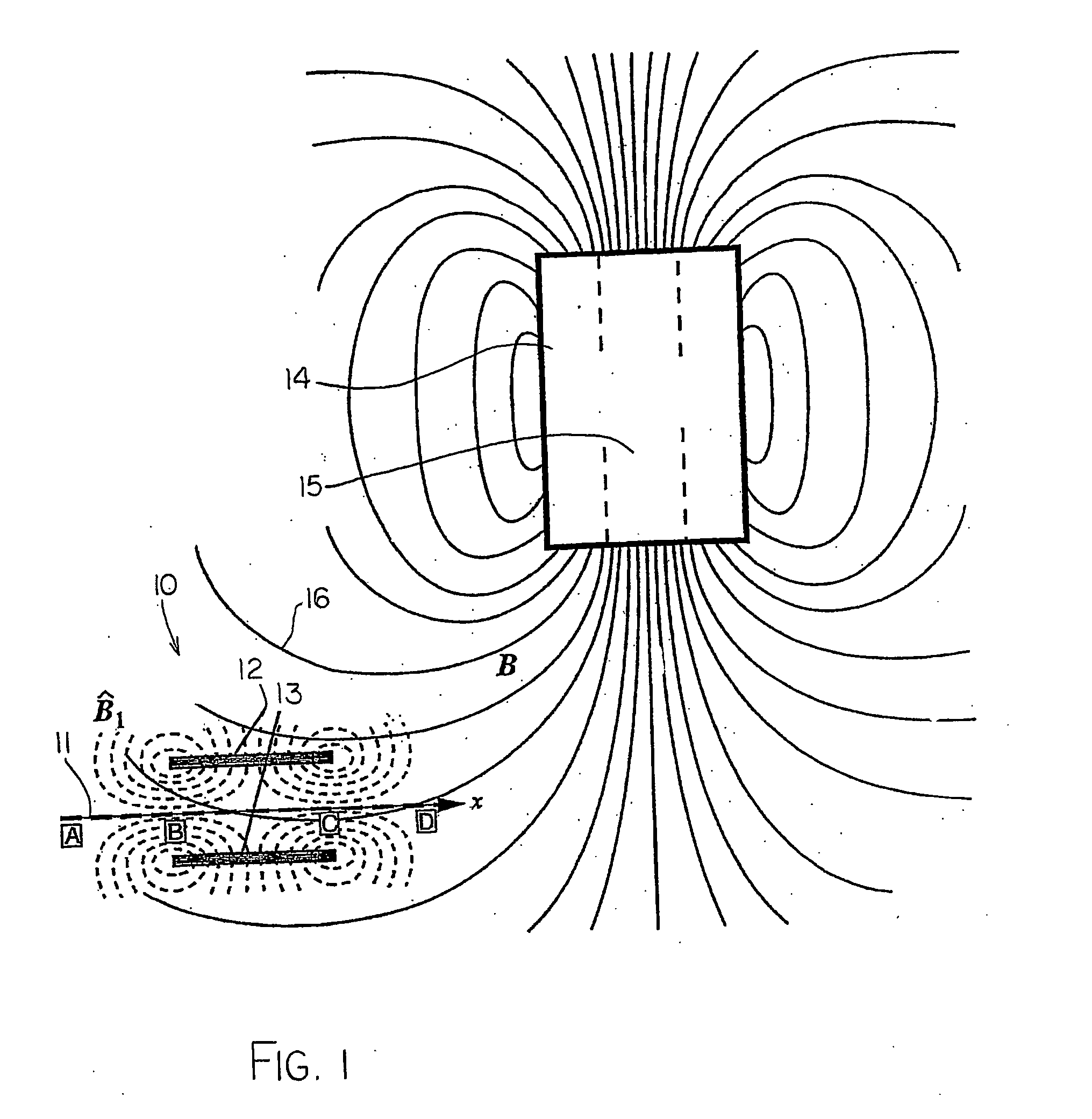
[0028] The apparatus for detecting a ferromagnetic object is generally indicated at 10 and comprises guides forming a path 11 between a pair of sensor coils 12 and 13. The sensor coils are arranged so that the path 11 is located in the fringe field of a magnet 14 of a magnetic resonance imaging system.

[0029] The construction arrangement of the magnet can vary and is well known to one skilled in the art so that further detail of the magnetic resonance imaging system is not necessary here. The magnet however forms a main field within a longitudinal bore 15 of the magnet where the sample to be analysed is located. The magnet, however, forms a fringe field including field lines schematically indicated at 16—again a very conventional well-known arrangement. At a suitable location in the fringe field, the path 11 is located so that the path at that position is generally parallel to the field lines. One example among many, wherein the field lines are generally at right angles to the axis ...


PUM


Abstract

An apparatus for detecting a potentially dangerous ferromagnetic object carried inadvertently by a person approaching the magnet of a magnetic resonance imaging system (14) uses the fringe field (16) of the magnet and provides guide members (11) defining a path along which the person is prescribed to pass. The path (11) is generally or approximately parallel to the field at the path. At least one sense coil and generally two sets of sense coils (12, 13) are located on respective sides of the path (11) so that the movement of the ferromagnetic object in the field of the magnet causes a voltage to be generated in the sense coil.

Description

[0001] The invention relates to the detection of ferromagnetic objects and in particular, it relates to a method of and apparatus for detecting ferromagnetic objects of a variety of sizes in the magnetic field created by a high strength magnet such as the imaging magnet of a magnetic resonance imaging machine or other similar magnets. BACKGROUND OF THE INVENTION [0002] The inadvertent introduction of ferromagnetic objects into the space surrounding high strength magnets such as magnetic resonance imaging magnets and magnets used in magnet guided catheterisation presents an ongoing hazard to both patients and staff in clinical imaging facilities. Such objects, if brought too close to the large magnet that encompasses a patient during scanning, can effectively become missiles that can seriously injure or even kill patient and staff alike, and tragically, more than one fatality has occurred. It is believed that no device exists to protect against the danger. The term “high strength” us...

Claims


Application Information

Patent Timeline
IPC IPC(8): F02P17/00G01V3/08G01V3/10
CPCG01R33/288G01V3/10
Inventor HOULT, DAVID I.
Owner NAT RES COUNCIL OF CANADA
Why Eureka
Try Eureka