
Method for inspecting and monitoring building, structure, or facilities accompanying them

a technology for inspecting and monitoring buildings and facilities, applied in the direction of data switching networks, instruments, and conversion of sensor output using wave/particle radiation, etc., can solve the problems of increasing labor costs against the objective, reducing the stop time against the objective, and reducing the cost of inspection and monitoring facilities. , the effect of reducing the wiring cos

Inactive Publication Date: 2005-11-03
HITACHI LTD
View PDF6 Cites 27 Cited by
  • Summary
  • Abstract
  • Description
  • Claims
  • Application Information

AI Technical Summary

Benefits of technology

[0013] It is expected to reduce the cost of the inspection and the monitoring. For example, what is required is:

Problems solved by technology

Furthermore, assuring a power source for a sensor and other devices is also a big cost problem, especially when performing continuous monitoring in a place where wiring is difficult.
In order to realize the objective (1), it is necessary to perform continuous remote monitoring to find a problem such as deterioration before occurrence of a trouble and increase the monitoring items but this goes against the objective (2).
However, if the sensor is installed each time when inspection is performed, it becomes difficult to reduce the stop time against the objective (1) and the labor cost is increased against the objective (2).
Even when a wireless sensor network is used, the sensor itself may be expensive.
However, the conventional facility inspection / monitoring system has the problems described in the Background of the Invention.
However, still following problems remain.

Method used


Image

  • Method for inspecting and monitoring building, structure, or facilities accompanying them
  • Method for inspecting and monitoring building, structure, or facilities accompanying them
  • Method for inspecting and monitoring building, structure, or facilities accompanying them

Examples


embodiment 1

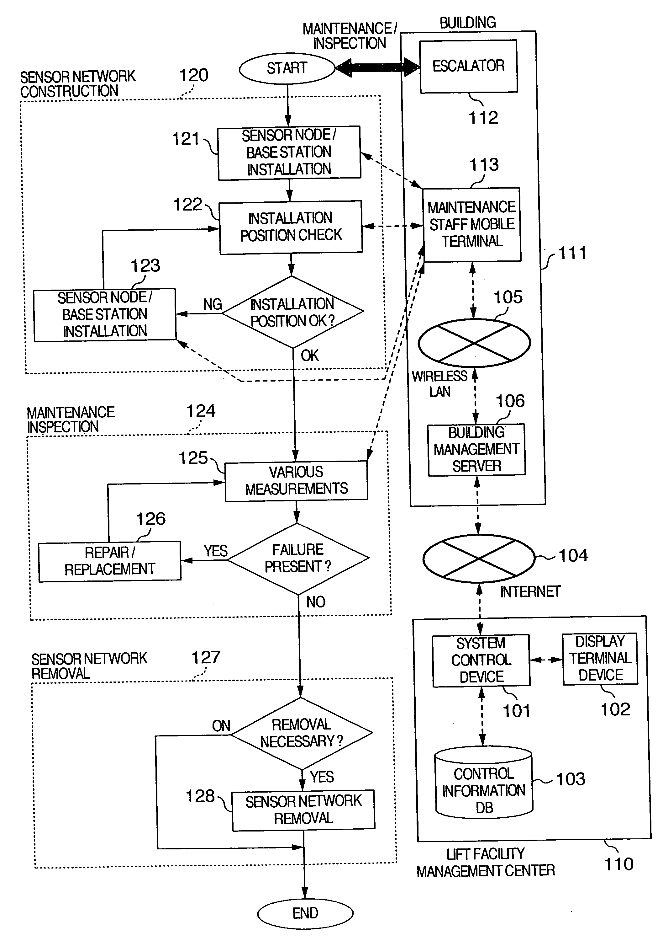
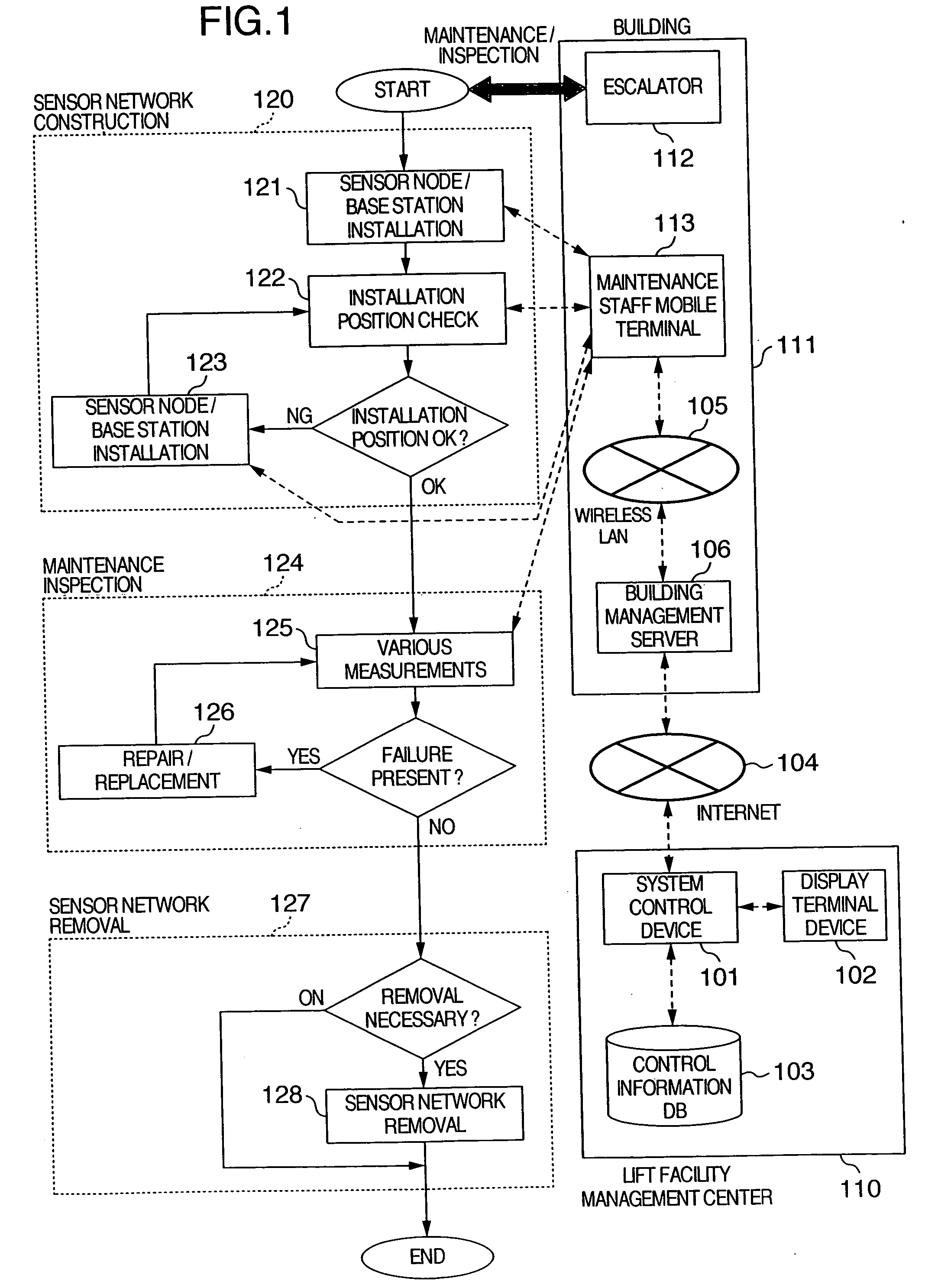
[0076] Here, the present invention is explained by using an example of periodical maintenance inspection of an escalator installed in a building. Here, for simplification of explanation, it is assumed that the escalator facility has sensors for the normal ordinary monitoring but no sensors utilized for periodical maintenance inspection.

[0077] Referring to FIG. 1, explanation will be given on the condition of the facility for maintenance inspection.

[0078] A maintenance company has a lift facility management center 110 and a system control device 101 for inspection and monitoring. The system control device 101 is connected to a display terminal device 102. The system control device 101 has a control information database 103 containing various information associated with the facilities (escalator in this example) to be managed. Here, the various information associated with the facilities to be managed include; a facility model (model number), a manufacturing number, an installation p...

embodiment 2

[0103] In the embodiment 1, an example has been given on maintenance inspection performed simultaneously on six escalators. However, it is also possible to perform maintenance inspection by dividing the six escalators into several groups. Firstly, an example will be given for inspection one by one. The device ID of the first escalator is inputted so as to construct a sensor network and perform inspection. After the inspection is completed, the sensor network is removed. Subsequently, the second escalator is inspected and then the third escalator and after.

[0104] When the embodiment 1 is compared to the embodiment 2, the following differences can be seen.

[0105] (1) In the embodiment 1, the six escalators should be stopped all at once. However, the time required for inspection is shorted as compared to the embodiment 2. The necessary number of sensor nodes and the base stations is greater than the embodiment 2.

[0106] (2) In the embodiment 2, the escalator which should be stopped si...

embodiment 3

[0107] The embodiment 1 has shown an example of method of the installation position acquisition 602 in the sensor node and base station installation 121. The embodiment 3 shows more simple method.

[0108] The method is to attach the RFID to the installation position in advance. The sensor node type and the base station to be installed are recorded on the RFID so that the maintenance staff searches / reads the RFID on the maintenance staff mobile terminal 113 or the RFID reader and installs an appropriate sensor node and a base station in the vicinity of the RFID. If the escalator 112 is depicted on the maintenance staff mobile terminal 113, search of the RFID becomes more effective.


PUM


Abstract

A method for performing maintenance inspection and monitoring of various structures and facilities by arranging a sensor on a moving portion of the facility of a building or a portion where wiring is difficult. The method includes a step of constructing a sensor network in accordance with the identification information on the facility, a step of acquiring the state of the facility by using the sensor network constructed, and a step of performing inspection or monitoring according to the acquired information on the state of the facility.

Description

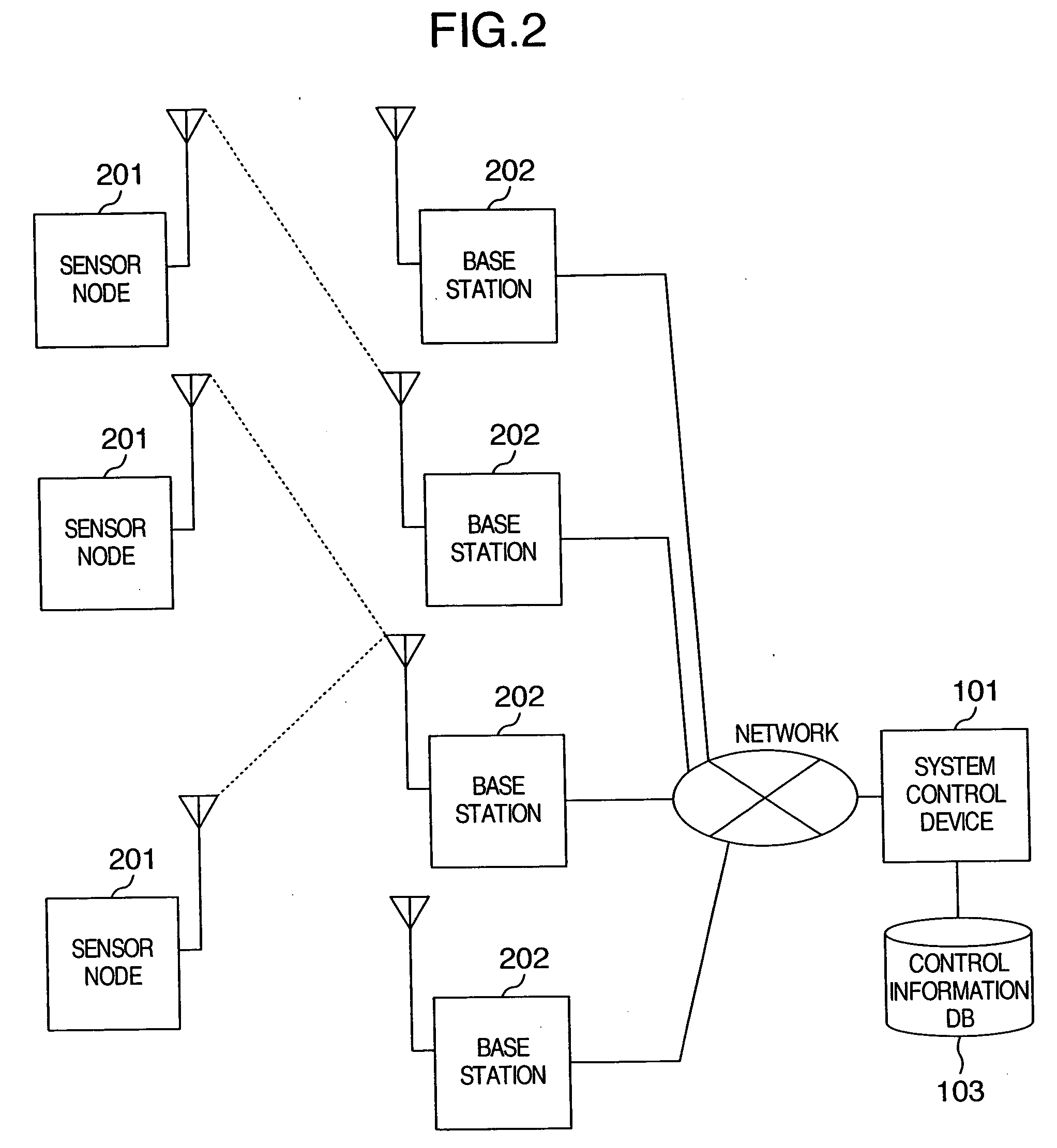
INCORPORATION BY REFERENCE [0001] The present application claims priority from Japanese application JP 2004-132480 filed on Apr. 28, 2004, the content of which is hereby incorporated by reference into this application. BACKGROUND OF THE INVENTION [0002] The present invention relates to a method for inspecting and monitoring a building including an apartment house and a structure such as a bridge as well as facilities installed in the building and the structure such as an elevator and an air conditioner and in particular, to an inspection and monitoring method using a sensor network. [0003] Recently the information technology has made a great progress and has been widely spread. The Internet has been spread in ordinary homes. Furthermore, mobile devices such as mobile telephones are spread and connected to the Internet. Moreover, a network such as wireless LAN is also widely spread in homes and offices. [0004] Moreover, recently, instead of the conventional bar code, RFID (Radio Freq...

Claims


Application Information

Patent Timeline
IPC IPC(8): G05B23/02G01D5/48G01D9/00G08B19/00G08C17/02H04Q9/00
CPCG01D9/005G01D21/00H04Q2209/60H04W84/18H04Q2209/47H04Q9/00
Inventor MATSUMOTO, KAZUHIKOARITSUKA, TOSHIYUKI
Owner HITACHI LTD
Learn More