

System and method for concurrent operation of multiple radar or active sonar systems on a common frequency
- Summary
- Abstract
- Description
- Claims
- Application Information
AI Technical Summary
Benefits of technology
Problems solved by technology
Method used
Image

Examples
Embodiment Construction
[0044] In the following detailed description, numerous specific details are set forth in order to provide a thorough understanding of the invention. However, it will be understood by those of ordinary skill in the art that the invention may be practiced without these specific details. In other instances, well-known methods, procedures and components have not been described in detail so as not to obscure the invention. Further, other hardware and software configurations can be used as is well known to those skilled in the art without departing from the invention. In addition, where considered appropriate, reference numerals may be repeated among the figures to indicate corresponding or analogous elements. It should be understood that the invention can also be applied to active sonar systems. However, for simplicity, the invention will be described for a network of radar systems.
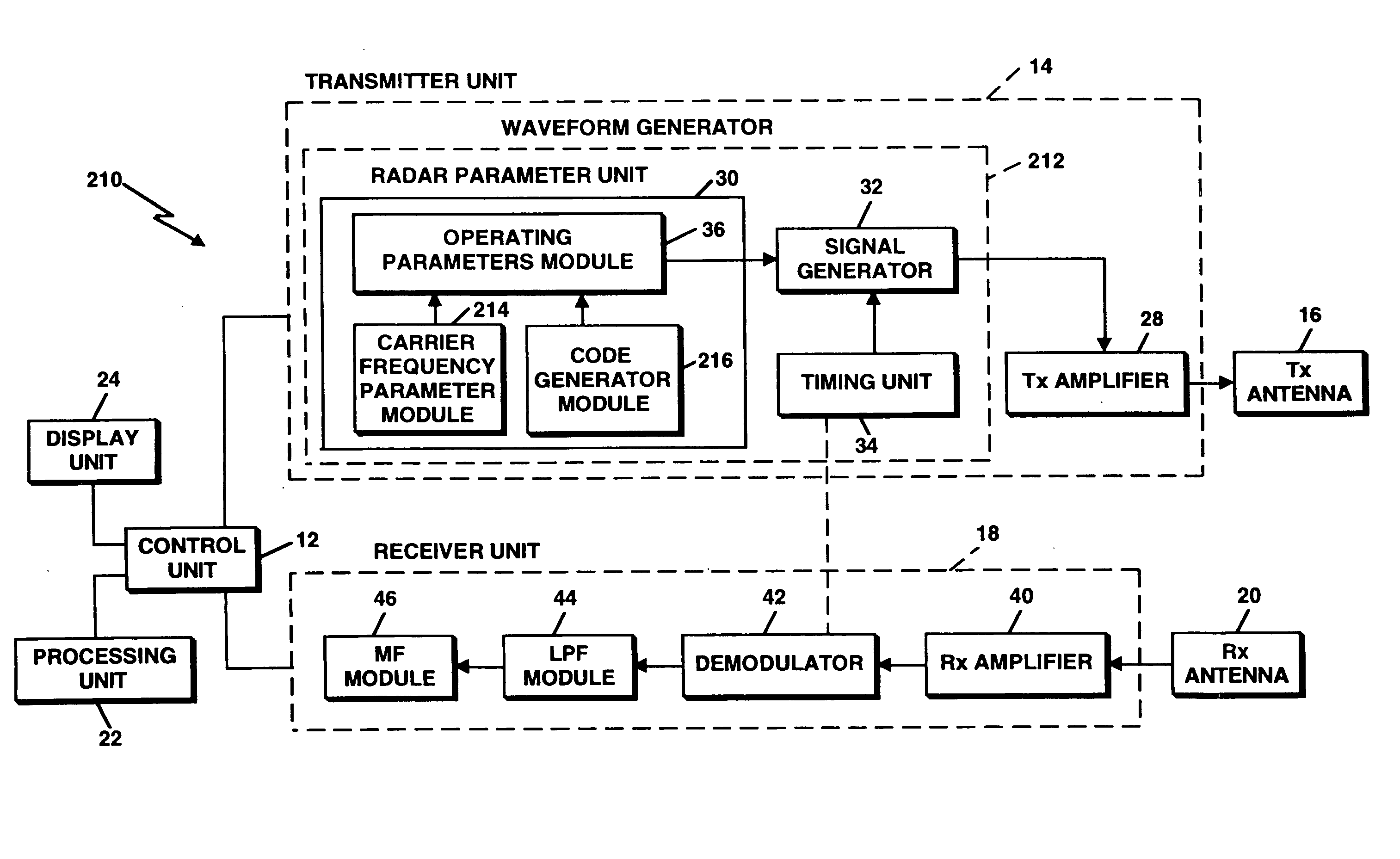
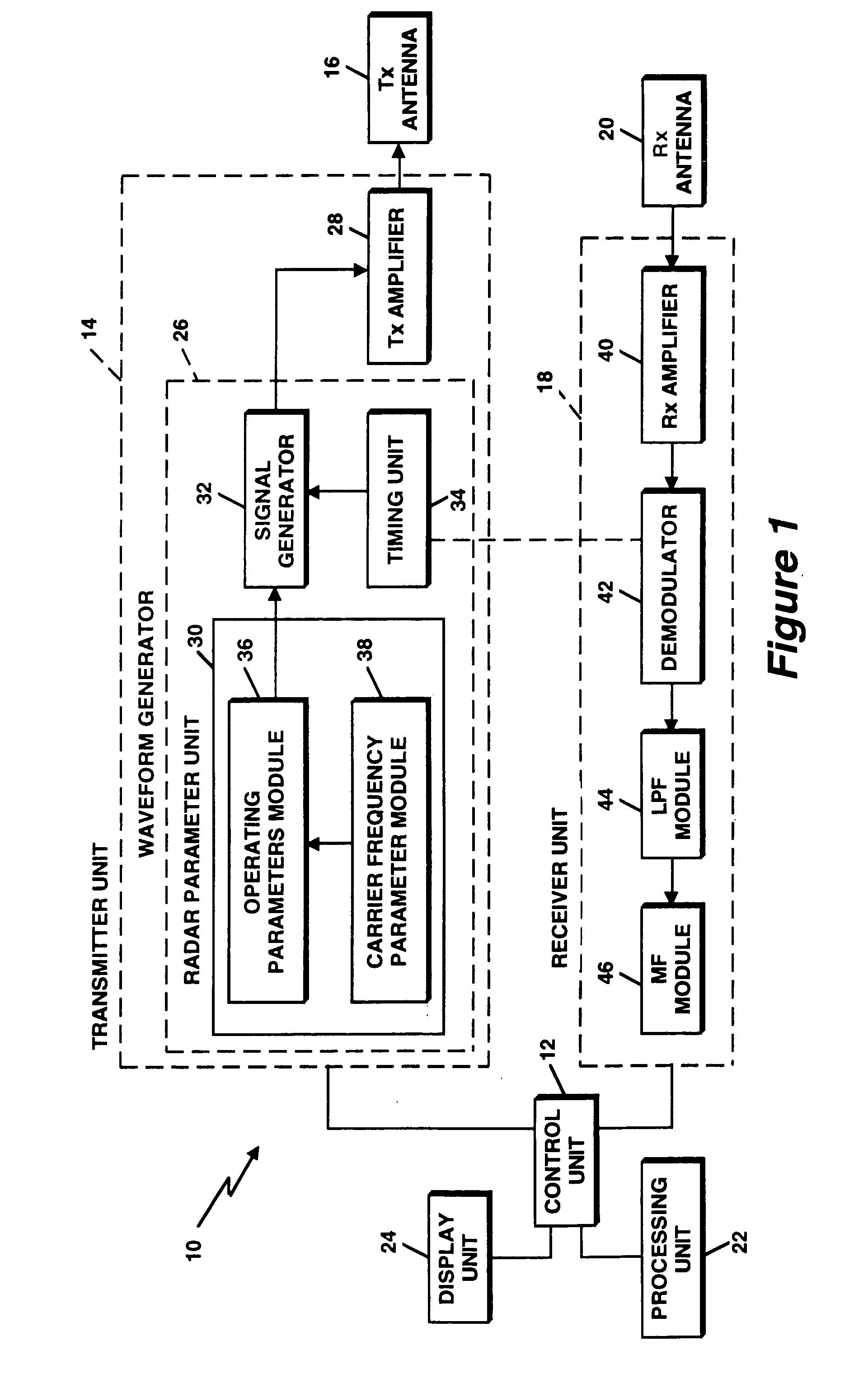
[0045] Referring now to FIG. 1, shown therein is a block diagram of a radar system 10 having a waveform ge...
PUM
 Abstract
Description
Claims
Application Information