High intensity photic stimulation system with protection of users

a high-intensity photic and user-protective technology, applied in the direction of counting objects on conveyors, applications, instruments, etc., can solve the problems of significant property damage, injury or death to others, and the urgency of restoring order cannot outweigh the undead use of deadly force on the civilian population, and achieve the effect of flash blindness

Inactive Publication Date: 2005-11-03
ER2S
View PDF2 Cites 20 Cited by
  • Summary
  • Abstract
  • Description
  • Claims
  • Application Information

AI Technical Summary

Benefits of technology

[0014] Briefly stated, in accordance with embodiments of the present invention, there are provided a method and system for providing high intensity photic stimulation for immobilizing or otherwise impeding or disabling a target subject while protecting the user. The photic stimulation system comprises a trigger signal circuit providing a trigger signal. A high intensity light source including a lamp is connected to the lamp trigger circuit. The lamp flashes in response to the trigger signal. A shutter viewer is provided which is switchable between a transmissive state and an attenuating state. The shutter viewer is connected to a shutter viewer trigger circuit which changes the state of the shutter viewer in response to...

Problems solved by technology

Individuals or crowds can cause significant property damage and injury or death to others.
However, the urgency of restoring order does not outweigh the undesirability of the use of deadly force on the civilian population.
High intensity light sources can cause “flash blindness,” which is temporary vision impairment.
Strobe lights can also cause seizures to debilitate target subjects who are epileptogenic.
Using dark, neutral density goggles to reduce light reaching a user's eyes is undesirable as a measure to reduce the effect of the flashing light.
The user's ability to see the when the light is not flashing may be severely limited, or if the user adapts to the dark filter, the resulting dilation of pupils in the eyes will render the user more susceptible to the light flashes because no time is provided for the eyes to adjust quickly to changing light levels.
It is pointed out that laser light may cause skin damage as well as permanent eye injury.
A device that dazzles at a long range may cause permanent damage at short range.
Damage is more likely when the laser light is used at night, when a target subject's pupil may have a nominal diameter of ...

Method used


Image

  • High intensity photic stimulation system with protection of users
  • High intensity photic stimulation system with protection of users
  • High intensity photic stimulation system with protection of users

Examples


Embodiment Construction

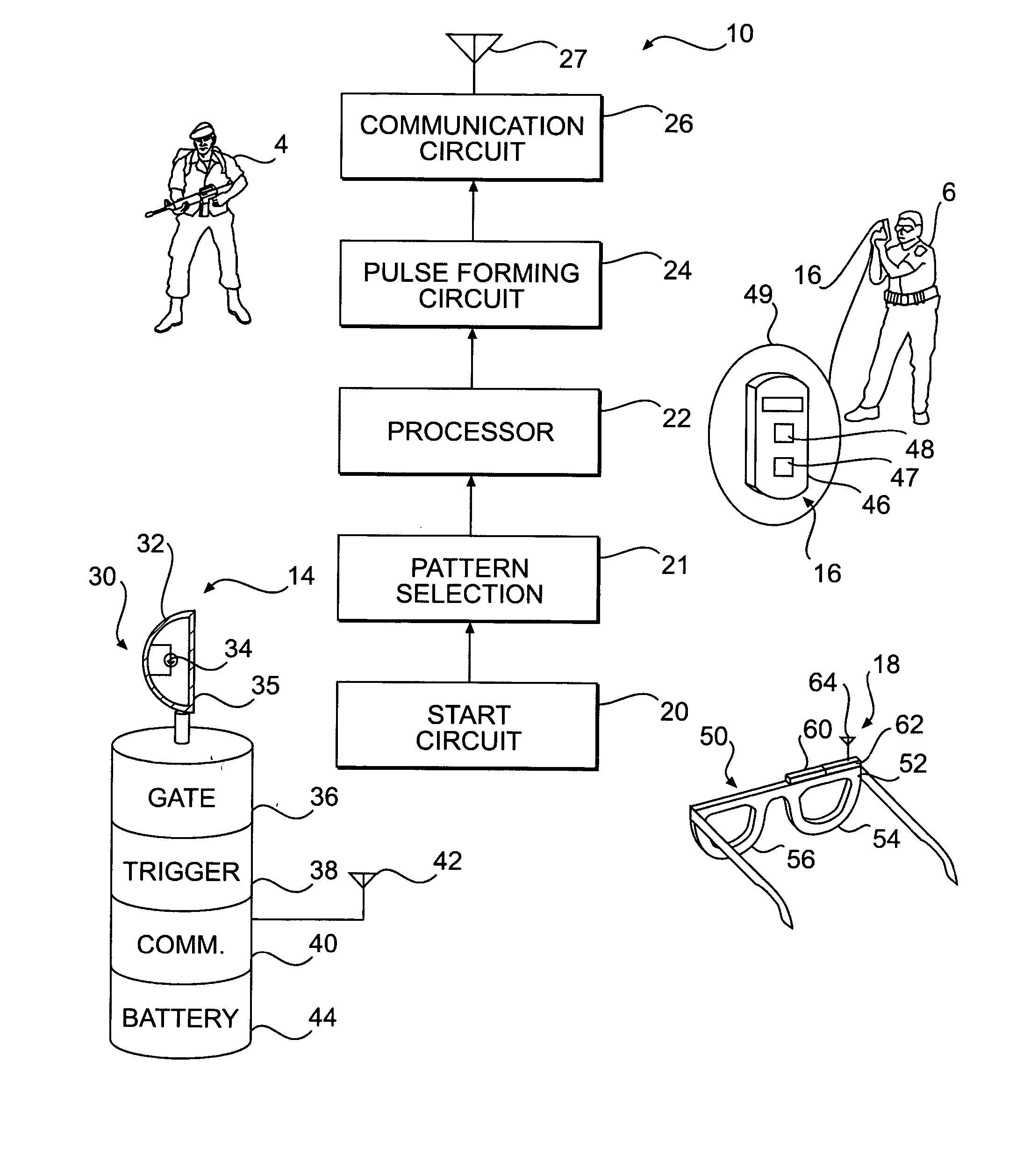
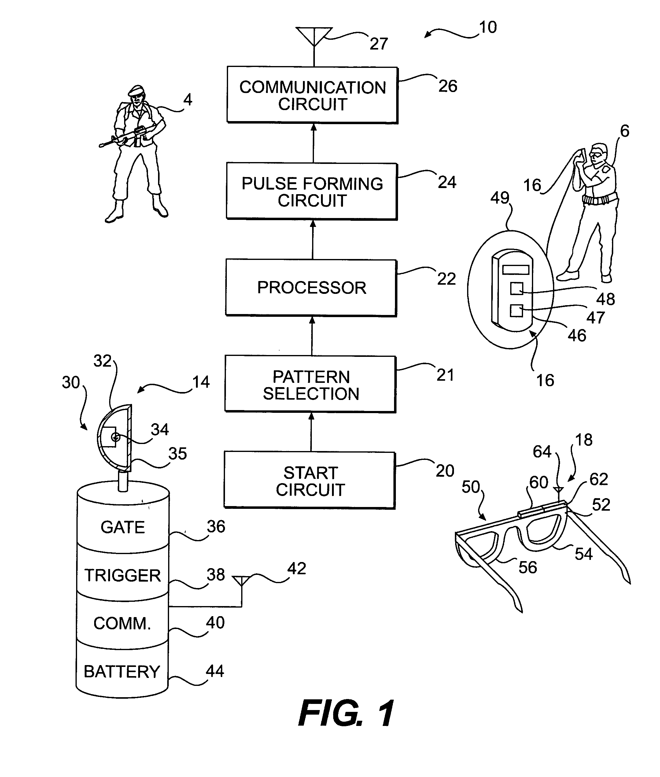
[0022]FIG. 1 is a block diagram of a system 1 constructed in accordance with an embodiment of the present invention. The system 1 is operable to provide flashing light for disabling a target subject 4 while providing a user 6 freedom to operate unimpeded by the flashing light. The target subject 4 is exposed to the disabling effects of the flashing light. Means are provided to render the flashing light virtually invisible to the user 6. “Target subject 4” or “user 6” may refer either to an individual or to a plurality of individuals. Individuals need not necessarily be human.

[0023] Subsystems in the system 1 comprise a control unit 10, a lighting subsystem 14 and a viewer subsystem 18. One or more control units 10 may be utilized at one time. The control unit 10 may be remote from the lighting subsystem 14 and the viewer subsystem 18. The control unit 10 could comprise a freestanding unit used on-site with the lighting subsystem 14. Alternatively or additionally, the control unit 1...


PUM

PropertyMeasurementUnit
Widthaaaaaaaaaa
Frequencyaaaaaaaaaa
Lightaaaaaaaaaa

Abstract

In a method and system to provide high intensity photic stimulation to disable target subjects, a high intensity light source is activated by trigger signals to produce light flashes in commanded patterns of duration and frequency. A user views a field illuminated through a shutter viewer such as shutter goggles. The goggles are gated to a light blocking state in response to trigger pulses. The light blocking state has a wider time width than the light flashes from the light source produced in response to the trigger pulses to avoid the need for close synchronization. The target subjects are exposed to the high intensity light flashes while the light flashes are blocked from the view of users. Due to a low duty cycle, the users' view through the shutter goggles is unaffected by the intermittent opacity of the shutter goggles.

Description

CROSS-REFERENCE TO RELATED APPLICATIONS [0001] This application claims priority to U.S. Provisional Patent Application Ser. No. 60 / 534,058 filed Jan. 5, 2004, the disclosure of which is incorporated herein by reference in its entirety.FIELD OF THE INVENTION [0002] The present subject matter relates to a method and system for high intensity photic stimulation. BACKGROUND OF THE INVENTION [0003] Photic stimulation comprises application of radiant energy to an organism at a frequency and intensity to which an organism will respond. Photic stimulation varies in its effect depending on wavelength, intensity and manner of application. Low intensity photic stimulation may be used for therapeutic purposes. However, high intensity photic stimulation may be used to apply non-lethal force having a disabling effect on humans or animals, who may be referred to as target subjects. High intensity light sources are incorporated in non-lethal weapons. “High intensity” in this context has an establis...

Claims


Application Information

Patent Timeline
IPC IPC(8): A61B6/00F41A33/02F41H13/00G02F1/1335
CPCF41H13/0087F41A33/02
Inventor CHOI, PETERWARE, KENNETH D.
Owner ER2S
Why Eureka
Try Eureka