Porous silicon filter for wavelength multiplexing or de-multiplexing

a technology of porous silicon and optical filters, applied in the field of optical filters, can solve the problems of requiring significant maintenance and easy failure of switches

Inactive Publication Date: 2005-11-03
CROSSFIBER +1
View PDF5 Cites 19 Cited by
  • Summary
  • Abstract
  • Description
  • Claims
  • Application Information

AI Technical Summary

Benefits of technology

[0016] In this switch any optical fiber in an input set of optical fibers, each carrying a number of communication beams, can be cross connected to any optical fiber in an output set of optical fibers. An alignment beam is added to and aligned co-axially with the communication beam carried by each fiber in the input set of optical fibers to define a communication-alignment beam for each fiber. Each communication-alignment beam is directed within a confined optical pathway to a specific exit aperture in an input array structure. The exit apertures for all of the communication-alignment beams are arranged in a pattern defining an input array so that each communication-alignment beam can be identified by the location of its exit aperture in the input array structure. Each communication-alignment beam is formed into a cross-connection beam by a micro-lens in a first lens micro-lens array. Each cross-connection beam is directed to a lens in a second lens array by two mirrors, a first mirror in a first mirror array and a second mirror in a second mirror array. The lens in the second micro-lens array focuses the communication beams into a specific input aperture of a confined optical pathway, preferably an optical fiber, in an output array structure. Each of the confined optical pathways in the output array structure is optically connected to an optical fiber of an output set of optical fibers. A first detector array located near the second lens array monitors the position of each alignment beam and provides position information to a processor for control of the mirrors in at least one of the mirror arrays. A dichroic beam splitter located optically between the first and second mirror arrays directs a first portion of the alignment beam to a second detector array that monitors beam direction of said first portion of each alignment beam and provides beam direction data to a processor programmed to control positions of the mirrors in the first mirror array. Preferably the first detector array is transparent to the communication beams permitting alignment beam detection while allowing the communication beams to pass through the detector array to the input apertures of the confined pathways in the output array structure. In this preferred arrangement the first detector array is optically located between the second lens array and the input aperture of a confined optical pathway in an output array structure. The porous silicon optical filters are utilized in the switch system as a de-multiplexer to filter out, from a set of communication beams in an optical fiber, a particular communication beam or a set of communications beams within a particular wavelength band from communication beams outside the band.

Problems solved by technology

Due to the extremely tight tolerances necessary for proper angular alignment of the various reflective elements, and because the open-loop responses of these reflective elements is insufficient to step perfectly into position, very sophisticated feedback control systems may be used, often resulting in these switches being prone to failure and requiring significant maintenance.

Method used


Image

  • Porous silicon filter for wavelength multiplexing or de-multiplexing
  • Porous silicon filter for wavelength multiplexing or de-multiplexing
  • Porous silicon filter for wavelength multiplexing or de-multiplexing

Examples


Embodiment Construction

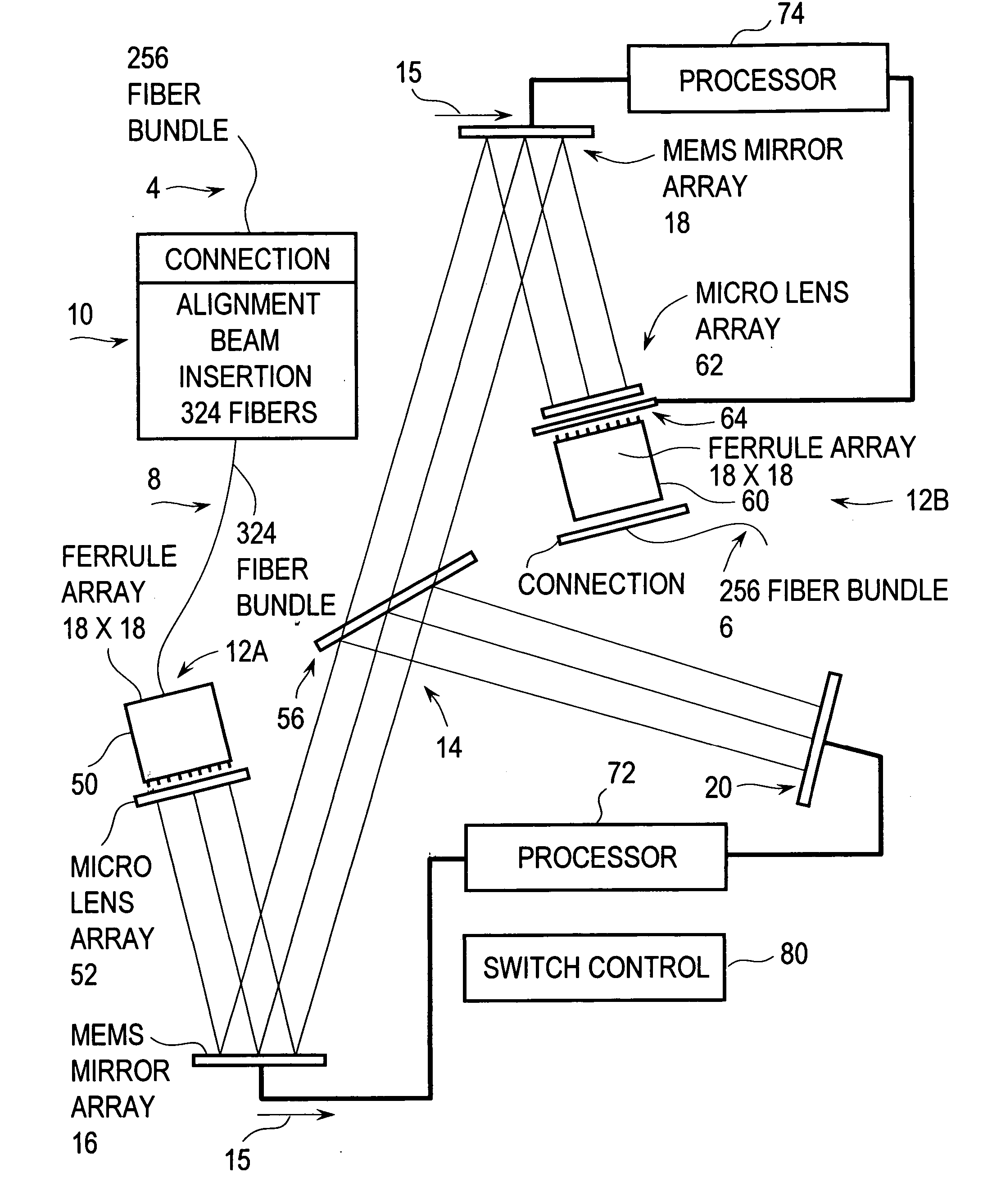
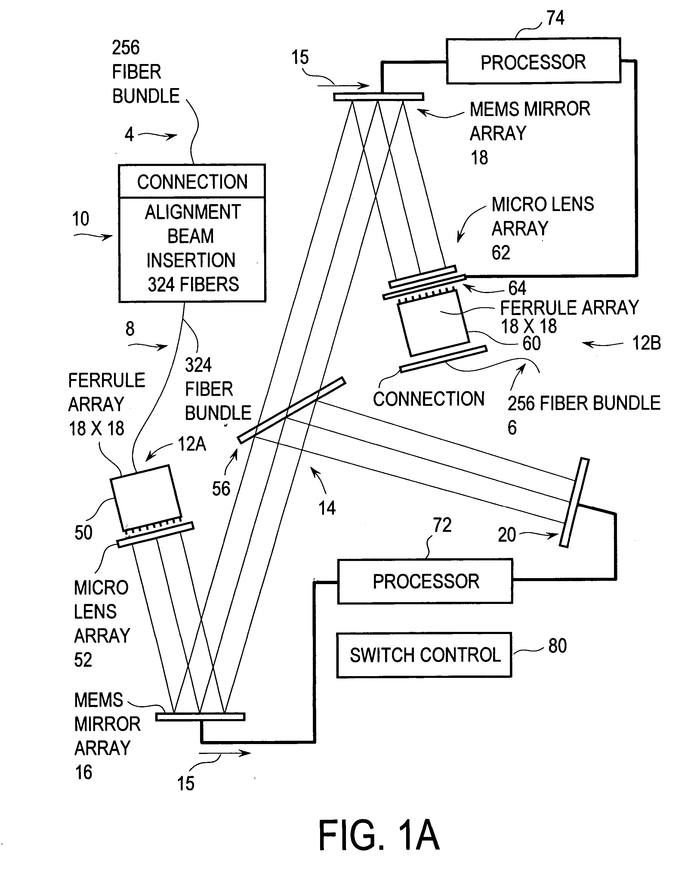
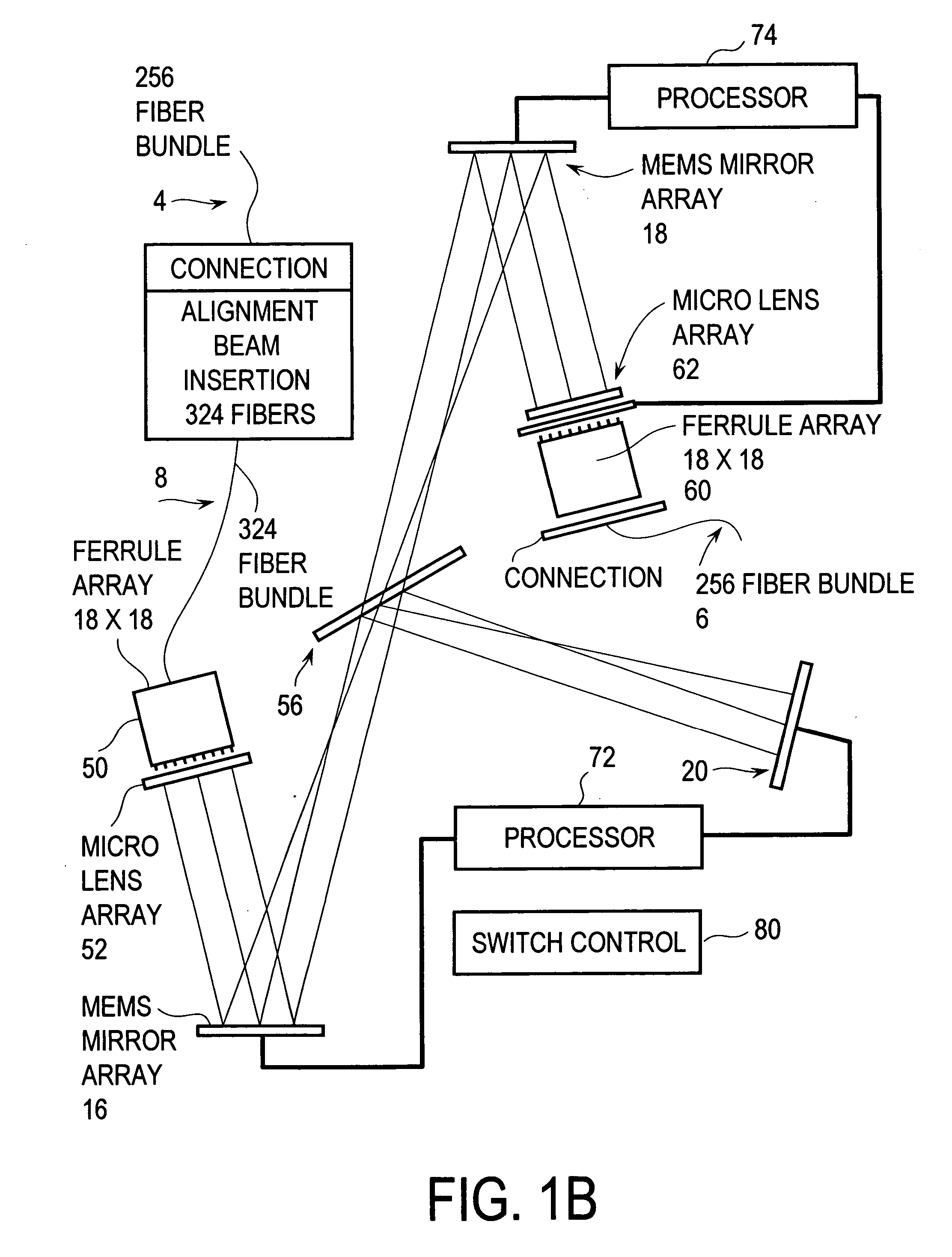
[0038]FIGS. 1A and 1B show an optical switch 2 for switching optical communication beams carried by the fibers of a first 256 (16×16) optical fiber bundle 4 into the fibers of a second 256 optical fiber bundle 6. The beams in any fiber of bundle 4 can be switched into any fiber of bundle 6. Bundles 4 and 6 may be a part of a large nation-wide communication system such as the one discussed in the section of this description entitled “Application in a Nation Scale Fiber Optic Network” in which each fiber is carrying information at a large number of separate frequencies. Or the bundles 4 and 6 may be a part of a multiplex or de-multiplex operation, such as an add-drop station, in which single or a small number of frequencies are carried by the individual fibers. The switch is divided into four basic portions: (1) an alignment beam insertion portion 10, (2) a beam input portion 12A, (3) a beam directing portion 14, and (4) a beam receiving portion 12B.

Alignment Beam Insertion Portion

[...


PUM

PropertyMeasurementUnit
currentaaaaaaaaaa
diametersaaaaaaaaaa
distanceaaaaaaaaaa

Abstract

A porous silicon filter for wavelength multiplexing and de-multiplexing. Preferred embodiments include rugate-type porous silicon filters with pores having continuously varying widths with pore depth an optical cross connect switch. In other preferred embodiments, the pores are filled with a material that changes index of refraction with changes in applied voltage, current or temperature. Important applications of these porous silicon filters are for multiplexing and de-multiplexing in fiber optic communication systems. For example, a preferred embodiment is an all optical fiber optic switch utilizing these filters.

Description

RELATED APPLICATIONS [0001] This Application is a Continuation-In-Part of U.S. patent applications Ser. No. 10 / 677,590 filed Oct. 2, 2003 and U.S. Ser. No. 10 / 838,070 filed May 3, 2004.FIELD OF THE INVENTION [0002] The present invention relates broadly to optical filters and in particular to porous silicon optical filters for fiber optic communication systems. BACKGROUND OF THE INVENTION Fiber Optic Communication [0003] Over the past several decades, the telecommunications industry has exploded, and the incorporation of optical fiber into this industry is revolutionizing the way information is transmitted. Communication systems which use optical fiber as the transmission media offer some significant advantages over past copper-based systems. These advantages include higher bandwidths and transmission rates, lower transmission losses, and greater signal isolation. There exist in the United States many million miles of optical fibers. Information must be routed through this maze of fi...

Claims


Application Information

Patent Timeline
Patent Type & Authority Applications(United States)
IPC IPC(8): G02B6/26G02B6/34G02B6/35G02F1/01G02F1/1333
CPCG02B6/29365G02B6/29367G02B6/3518G02B6/3556G02B6/356G02B6/357G02F2203/055G02B6/3588G02F1/011G02F1/0115G02F1/1326G02F2201/307G02B6/3584
Inventor BARRETT, TODD
Owner CROSSFIBER
Why Eureka
Try Eureka