Image sensing device and control method thereof

a technology of image sensing and control method, which is applied in the direction of exposure control, camera focusing arrangement, printers, etc., can solve the problems of underexposure of main object, inaccurate exposure value, and inability to accurately measure the exposure valu

Inactive Publication Date: 2005-11-03
CANON KK
View PDF1 Cites 8 Cited by
  • Summary
  • Abstract
  • Description
  • Claims
  • Application Information

AI Technical Summary

Benefits of technology

[0008] The present invention has been made in consideration of the aforementioned problems, and has as its object to provide a technique for shooting an image on the basis of an appropriate exposure value by eliminating the influence of a change in optical condition due to the lens extension position. It is another object of the present invention to provide a technique that allows appropriate strobe shooting which is hardly influenced by the reflectance of an object.

Problems solved by technology

However, when automatic exposure shooting is performed by controlling object reflected light of the strobe, and a sub object with a high reflectance such as glass, a mirror, or the like is present near a main object, the exposure value is determined under the influence of the sub object with the high reflectance and, consequently, the main object is underexposed.
However, since pre-light emission is made to determine the main light emitting amount of the strobe irrespective of the in-focus state of the camera, the exposure value often becomes inaccurate.
When an abnormal reflecting object such as glass or the like is present upon pre-light emission, underexposure occurs due to that influence.
In patent reference 4, the influence of underexposure when an abnormal reflecting object such as glass or the like is present can be minimized, but it is difficult to obtain an appropriate exposure value when an object falls outside the light control range.

Method used


Image

  • Image sensing device and control method thereof
  • Image sensing device and control method thereof
  • Image sensing device and control method thereof

Examples


Embodiment Construction

[0022] Preferred embodiments of the present invention will be described in detail hereinafter with reference to the accompanying drawings.

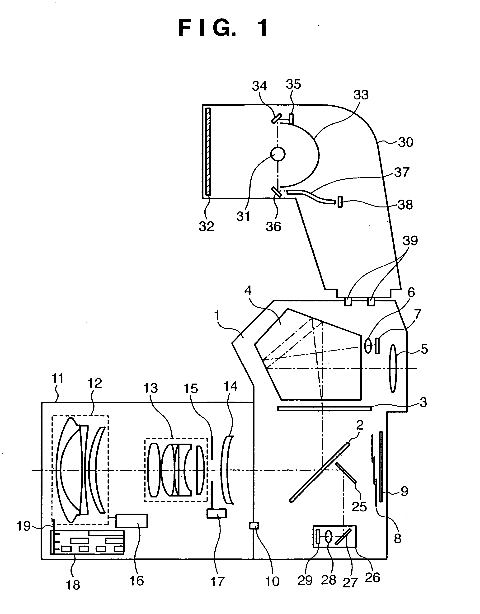
[0023]FIG. 1 is a sectional view of an optical system when a strobe is mounted on a single-lens reflex camera according to this embodiment.

[0024] Referring to FIG. 1, reference numeral 1 denotes a camera body, on the front surface of which a shooting lens 11 is mounted. The camera body 1 houses optical members, mechanical members, an electric circuit, a film or image sensing element such as a CCD or the like, and so forth, and can shoot a photo or image. Reference numeral 2 denotes a main mirror, which is obliquely inserted into a shooting optical path in a viewfinder observation state, and escapes outside the shooting optical path in a shooting state. The main mirror 2 is a half mirror, which passes about half light rays of those coming from an object toward a focus detection optical system (to be described later) when it is obliquely inserted ...


PUM


Abstract

This invention allows to shoot an image using correct object distance information and light emitting amount when the main light emitting amount upon shooting an object image is calculated by making the pre-light emission after the auto-focusing process. To this end, when a predetermined button independent of a release button is operated, a focusing process is executed first. Then, photometry is made while inactivating a strobe, i.e., under available light, and an exposure value is determined based on an object distance. Then, pre-light emission is made, light reflected by the object in the pre-light emission is measured, and the photometry result under the available light is subtracted from that in the pre-light emission, so as to obtain a brightness value of object reflected light of only the pre-light emission. This brightness value is corrected to be equal to lower than an allowable maximum value depending on the object distance to compute a main light emitting amount. After that, when the release button is operated, the strobe is driven on the basis of the determined main light emitting amount, and shooting is made using the determined exposure value.

Description

FIELD OF THE INVENTION [0001] The present invention relates to a technique for shooting an image after making pre-light emission toward an object in order to obtain an appropriate exposure value. BACKGROUND OF THE INVENTION [0002] Upon shooting a picture with strobe, automatic light control is normally executed by making a pre-light emission, measuring the objects reflected light, and determining the amount of main light needed on the basis of the photometry result. [0003] Normally, a series of these processes are done depending on the operation state of a release switch (SW). More specifically, main light emission is performed after pre-light emission, photometry, and determination of the main light emitting amount are made while the release SW is pressed at the full stroke position. [0004] Also, an automatic light control camera is known (e.g., Japanese Patent Laid-Open Nos. 61-156239, 61-156240, and 60-61733). That is, a member independent from the release SW makes pre-light emis...

Claims


Application Information

Patent Timeline
Patent Type & Authority Applications(United States)
IPC IPC(8): G02B7/28G02B7/34G03B7/16G03B13/32G03B13/36G03B15/03G03B15/05G03B19/18
CPCG03B7/16
Inventor FUKUI, HAJIME
Owner CANON KK
Why Eureka
Try Eureka