

Method of controlling operation of fuel gas production apparatus
- Summary
- Abstract
- Description
- Claims
- Application Information
AI Technical Summary
Benefits of technology
Problems solved by technology
Method used
Image

Examples
first embodiment
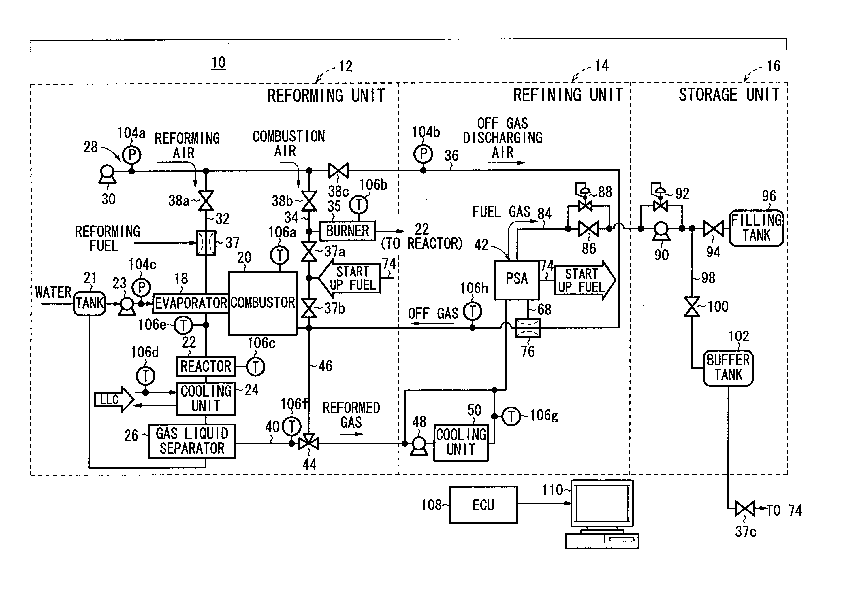
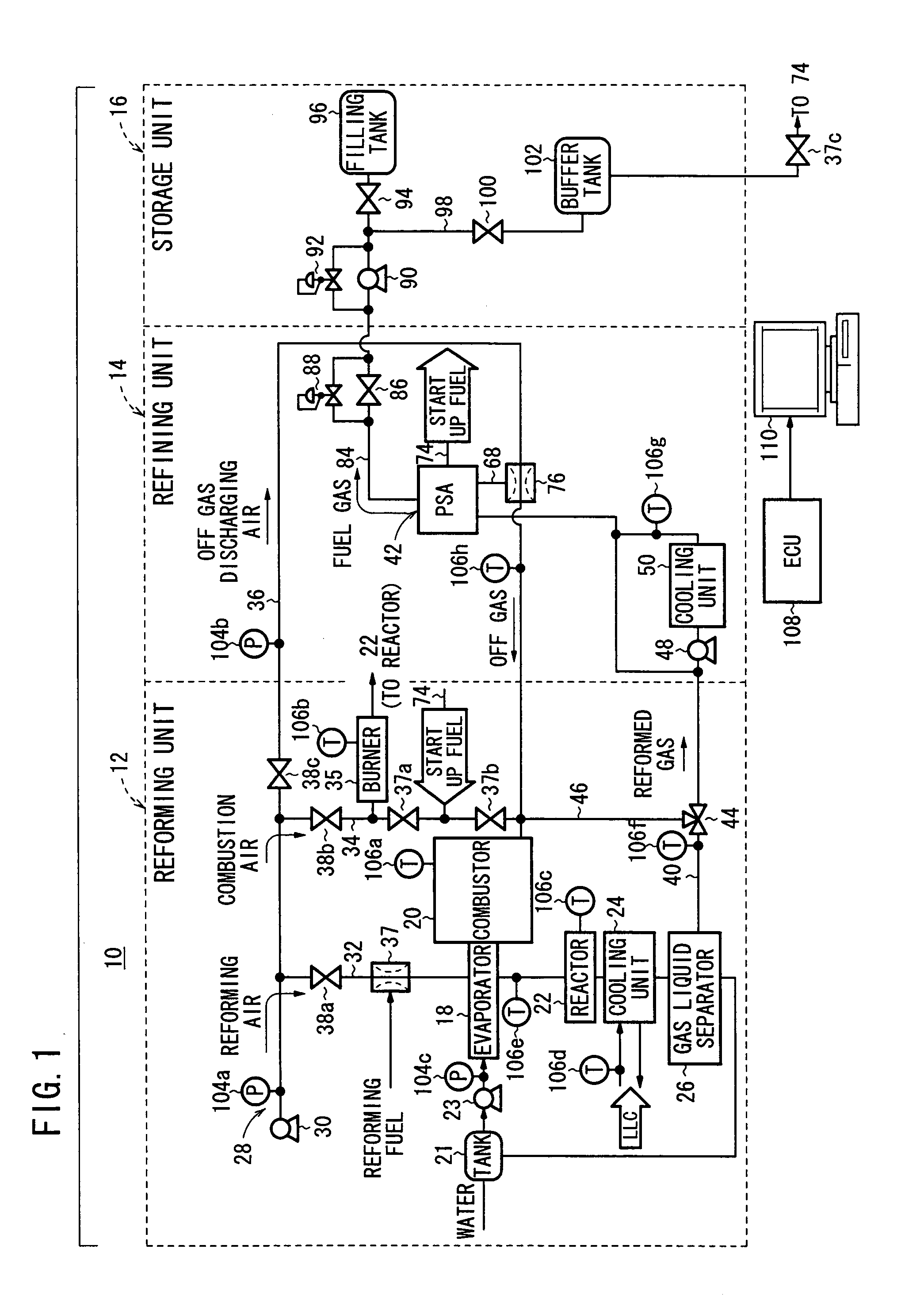
[0034]FIG. 1 is a diagram schematically showing a home fuel gas refining system (fuel gas production apparatus) 10 for carrying out a control method according to the present invention.
[0035] The home fuel gas refining system 10 includes a reforming unit 12, a refining unit 14, and a storage unit 16. The reforming unit 12 reforms a hydrogen-containing fuel, e.g., a fuel containing hydrocarbon such as methane or propane (hereinafter also referred to as the “reforming fuel”) to obtain a hydrogen-rich gas (hereinafter also referred to as the “reformed gas”). The refining unit 14 refines the hydrogen rich gas to produce a highly pure hydrogen gas (hereinafter also referred to as the “fuel gas”). The storage unit 16 stores the fuel gas.
[0036] The reforming unit 12 includes an evaporator 18 for evaporating the reforming fuel using combustion catalyst. A combustor (heating unit) 20 such as a burner is provided for the evaporator 18. A water supply tank 21 is connected to the evaporator 18 ...
second embodiment
[0087] The home fuel gas production system 210 communicates with and controls auxiliary devices. In particular, in the second embodiment, various abnormal conditions of the home fuel gas production system 210 are detected based on detection signals from the pressure sensors 104a through 104g and the temperature sensors 106a, 106c, and 106h. The home fuel gas production system 210 includes, e.g., an ECU (Electric Control Unit) 108 as a control unit for determining whether the detected abnormal condition corresponds to a stop pattern among a plurality of predetermined stop patterns, and performing a stop process according to the corresponding predetermined stop pattern.
[0088] The ECU 108 sends various items of information such as information about an abnormal condition to the control panel 110. If it is determined that the problem of the abnormal condition cannot be eliminated by the self-repair process, the abnormal position and information about the abnormal condition are notified t...
PUM
 Abstract
Description
Claims
Application Information