Transmitting apparatus and radio communication apparatus

a technology of transmission apparatus and radio communication apparatus, which is applied in the direction of transmission monitoring, modulation, gain control, etc., can solve the problems of increased heat generation, reduced power efficiency of linear amplifiers, and large apparatus size, so as to improve power efficiency and control the power of transmission output. , the effect of wide transmission output power control rang

Inactive Publication Date: 2005-11-03
PANASONIC CORP
View PDF6 Cites 49 Cited by
  • Summary
  • Abstract
  • Description
  • Claims
  • Application Information

AI Technical Summary

Benefits of technology

[0013] It is an object of the present invention to provide a transmitting apparatus and radio communication apparatus...

Problems solved by technology

This kind of linear amplifier has excellent linearity, but because it constantly consumes power associated with a DC bias component, so this kind of the linear amplifier has lower power efficiency than a class C, class D, class E or similar nonlinear amplifier.
Consequently, when this kind of high-frequency power amplifier is applied to a portable radio device that uses a battery as its power source, usage time has been shortened due to the large power consumption of the high-frequency power amplifier.
Also, when this kind of high-frequency power amplifier is applied to a base...

Method used


Image

  • Transmitting apparatus and radio communication apparatus
  • Transmitting apparatus and radio communication apparatus
  • Transmitting apparatus and radio communication apparatus

Examples


embodiment 1

(Embodiment 1)

[Configuration of Transmitting Apparatus]

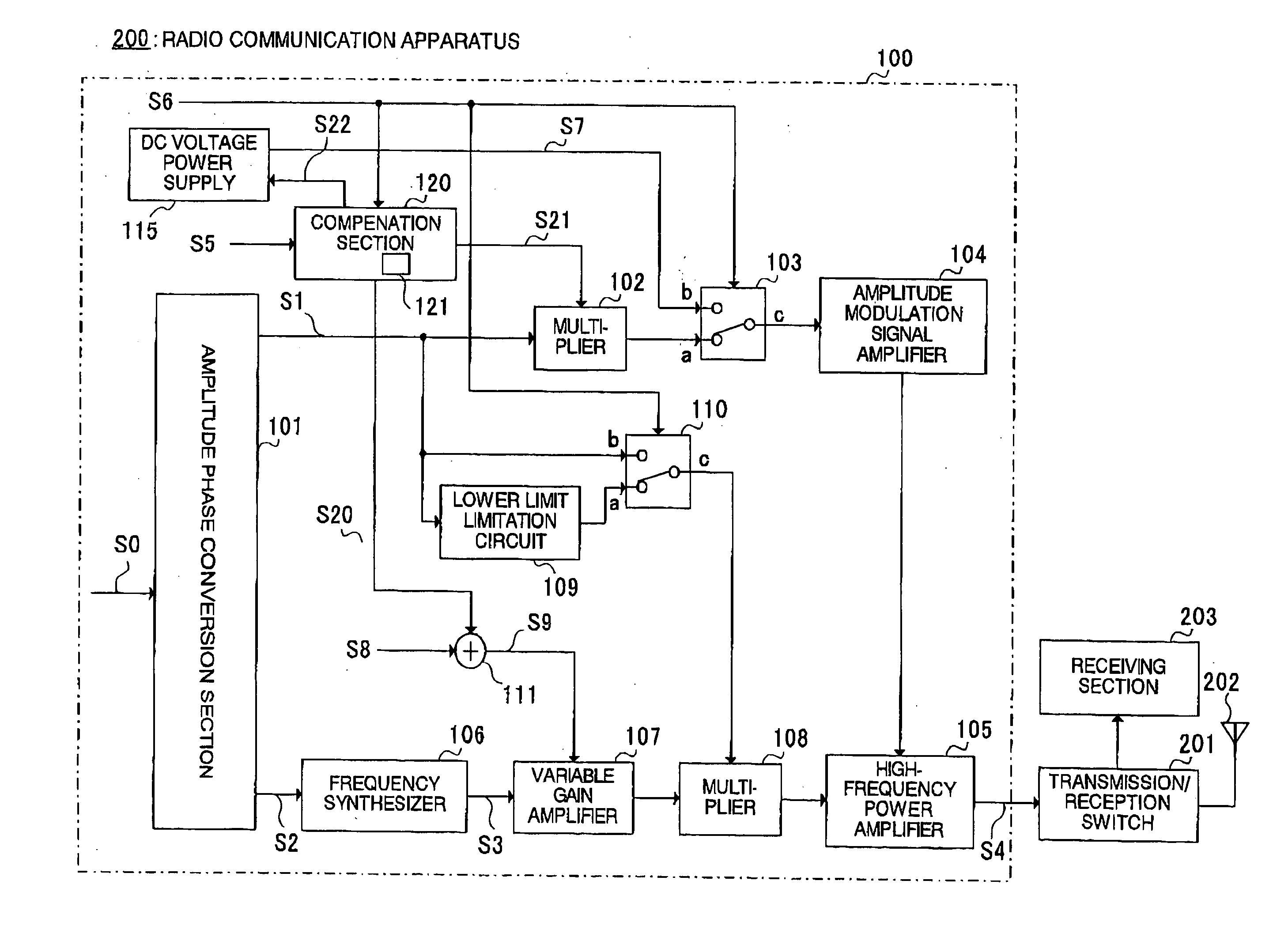
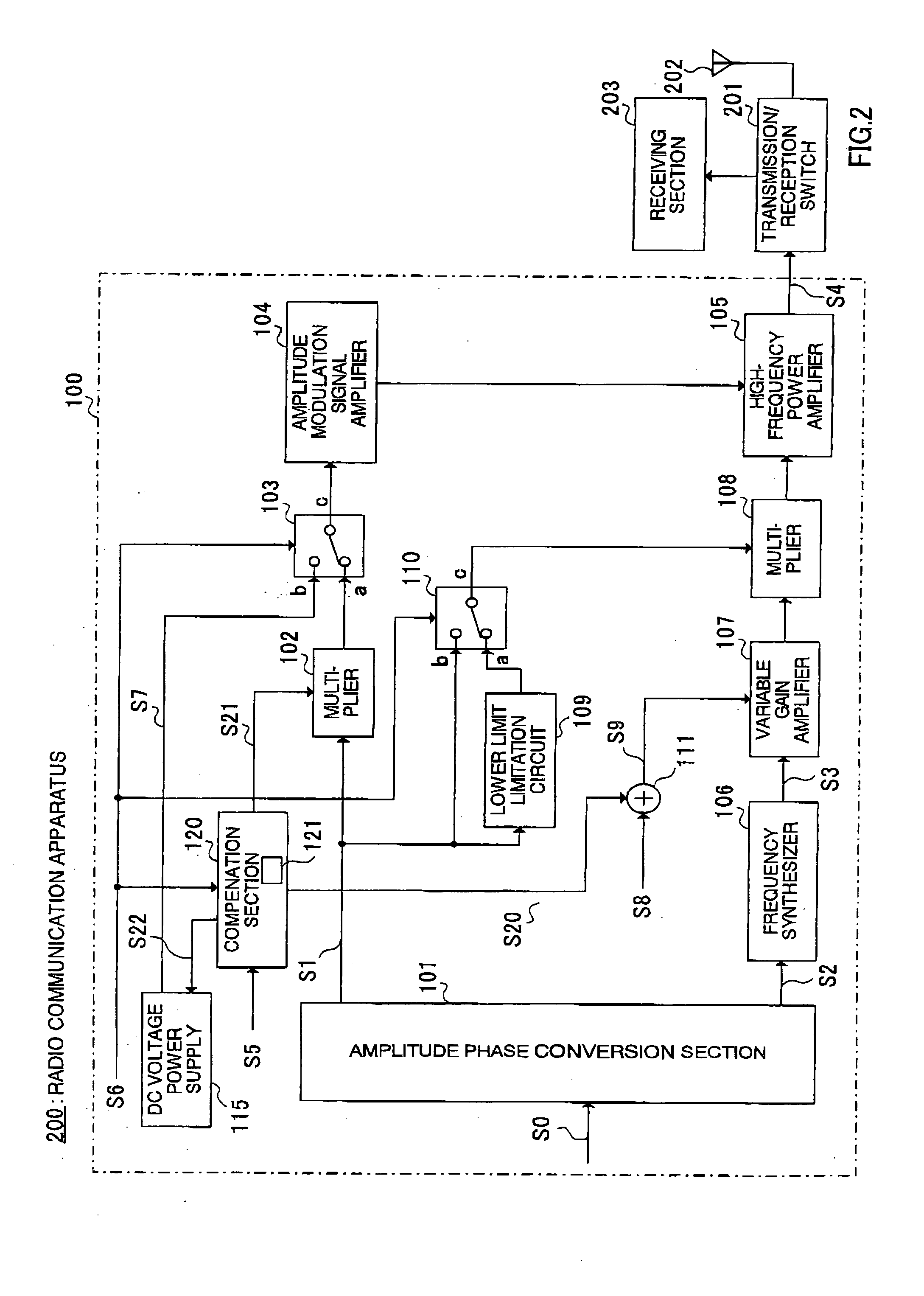
[0031]FIG. 2 is a block diagram showing the general configuration of a radio communication apparatus according to Embodiment 1 of the present invention.

[0032] As shown in FIG. 2, a radio communication apparatus 200 according to Embodiment 1 of the present invention is equipped with a transmitting apparatus 100, a transmission / reception switch 201, an antenna 202, and a receiving section 203.

[0033] Transmitting apparatus 100 is equipped with an amplitude phase conversion section 101, a compensation section 120, a multiplier 102, a switch 103, an amplitude modulation signal amplifier 104, a high-frequency power amplifier 105, a frequency synthesizer 106, a variable gain amplifier 107, a multiplier 108, a lower limit limitation circuit 109, a switch 110, an adder 111, and a DC voltage power supply 115.

[0034] Amplitude phase conversion section 101 receives a baseband modulation signal S0 and separates this signal into a baseband...

embodiment 2

(Embodiment 2)

[0079] Embodiment 2 of the present invention will now be described with reference to the accompanying drawings. FIG. 8 is a block diagram showing the configuration of a radio communication apparatus according to Embodiment 2 of the present invention. Configuration elements in Embodiment 2 of the present invention identical to those in Embodiment 1 of the present invention are assigned the same codes as in Embodiment 1, and descriptions thereof are omitted.

[Configuration of Transmitting Apparatus and Radio Communication Apparatus]

[0080] As shown in FIG. 8, a transmitting apparatus 100 according to Embodiment 2 of the present invention and a radio communication apparatus 200 in which this transmitting apparatus 100 is incorporated are equipped with a power detection section 141, a compensation value calculation section 142, and a compensation section 145, in addition to the configurations of transmitting apparatus 100 and radio communication apparatus 200 according to ...

embodiment 3

(Embodiment 3)

[0100] Embodiment 3 of the present invention will now be described with reference to the accompanying drawings. FIG. 13 is a block diagram showing the configuration of a radio communication apparatus according to Embodiment 3 of the present invention. Configuration elements in Embodiment 3 of the present invention identical to those in Embodiments 1 and 2 of the present invention are assigned the same codes as in Embodiments 1 and 2, and descriptions thereof are omitted.

[Configuration of Transmitting Apparatus and Radio Communication Apparatus]

[0101] As shown in FIG. 13, a transmitting apparatus 100 and radio communication apparatus 200 according to Embodiment 3 of the present invention are equipped with a switch 160 provided in place of coupler 140 of transmitting apparatus 100 and radio communication apparatus 200 according to Embodiment 2 of the present invention, and a switch 161 that switches between input of gain control signal S5 and a compensation reference s...


PUM


Abstract

A transmitting apparatus 100 operates a high-frequency power amplifier 105 as a nonlinear amplifier in a first mode, and operates high-frequency power amplifier 105 as a linear amplifier in a second mode. When high-frequency power amplifier 105 is operated as a nonlinear amplifier, the input level of high-frequency power amplifier 105 is varied by a variable gain amplifier 107 in accordance with the average output power of a transmit signal. Transmitting apparatus 100 is also provided with a compensation table 121 for reducing error in high-frequency power amplifier 105 mode switching operations.

Description

BACKGROUND OF THE INVENTION [0001] 1. Field of the Invention [0002] The present invention relates to a transmitting apparatus and radio communication apparatus, and more particularly to a transmitting apparatus and radio communication apparatus that perform power amplification of a transmit signal to output that signal. [0003] 2. Description of the Related Art [0004] Heretofore, a class A or class AB linear amplifier has been used to linearly amplify an envelope fluctuation component in a high-frequency power amplifier that amplifies a modulation signal containing an envelope fluctuation component. This kind of linear amplifier has excellent linearity, but because it constantly consumes power associated with a DC bias component, so this kind of the linear amplifier has lower power efficiency than a class C, class D, class E or similar nonlinear amplifier. Consequently, when this kind of high-frequency power amplifier is applied to a portable radio device that uses a battery as its p...

Claims


Application Information

Patent Timeline
IPC IPC(8): H01Q11/12H03G3/30H04B1/04
CPCH03G3/3042
Inventor NAKAMURA, MAKIARAYASHIKI, MAMORU
Owner PANASONIC CORP
Why Eureka
Try Eureka