
Control apparatus for controlling stepped automatic transmission of vehicle

Active Publication Date: 2005-11-03
TOYOTA JIDOSHA KK
View PDF8 Cites 29 Cited by
  • Summary
  • Abstract
  • Description
  • Claims
  • Application Information

AI Technical Summary

Benefits of technology

[0007] The present invention was made in the light of the background art discussed above. It is therefore an object of the present invention to provide a control apparatus capable of controlling a stepped automatic transmission which has an input shaft mechanically connectable to an engine and which is shifted to a selected one of a plurality of drive positions in such a manner that minimizes or reduces a shift shock occurred upon completion of the shifting action in the transmission. This object of the invention may be achieved according to any one of first through eighteenth aspects of the invention which are described below.

Problems solved by technology

In this instance, the quick stop of the change of the engine speed causes an elastic torsional vibration in a power transmitting path between the engine and a wheel of the vehicle, thereby leading to a possible occurrence of a shift shock.
Such a problem is encountered also in a vehicle in which a fluid-operated power transmitting device equipped with a lock-up clutch is disposed between the engine and the transmission.
That is, the vehicle having the fluid-operated power transmitting device suffers from the same problem, when the shifting action of the transmission is effected with the lock-up clutch being placed in its engaged state.

Method used


Image

  • Control apparatus for controlling stepped automatic transmission of vehicle
  • Control apparatus for controlling stepped automatic transmission of vehicle
  • Control apparatus for controlling stepped automatic transmission of vehicle

Examples


first embodiment

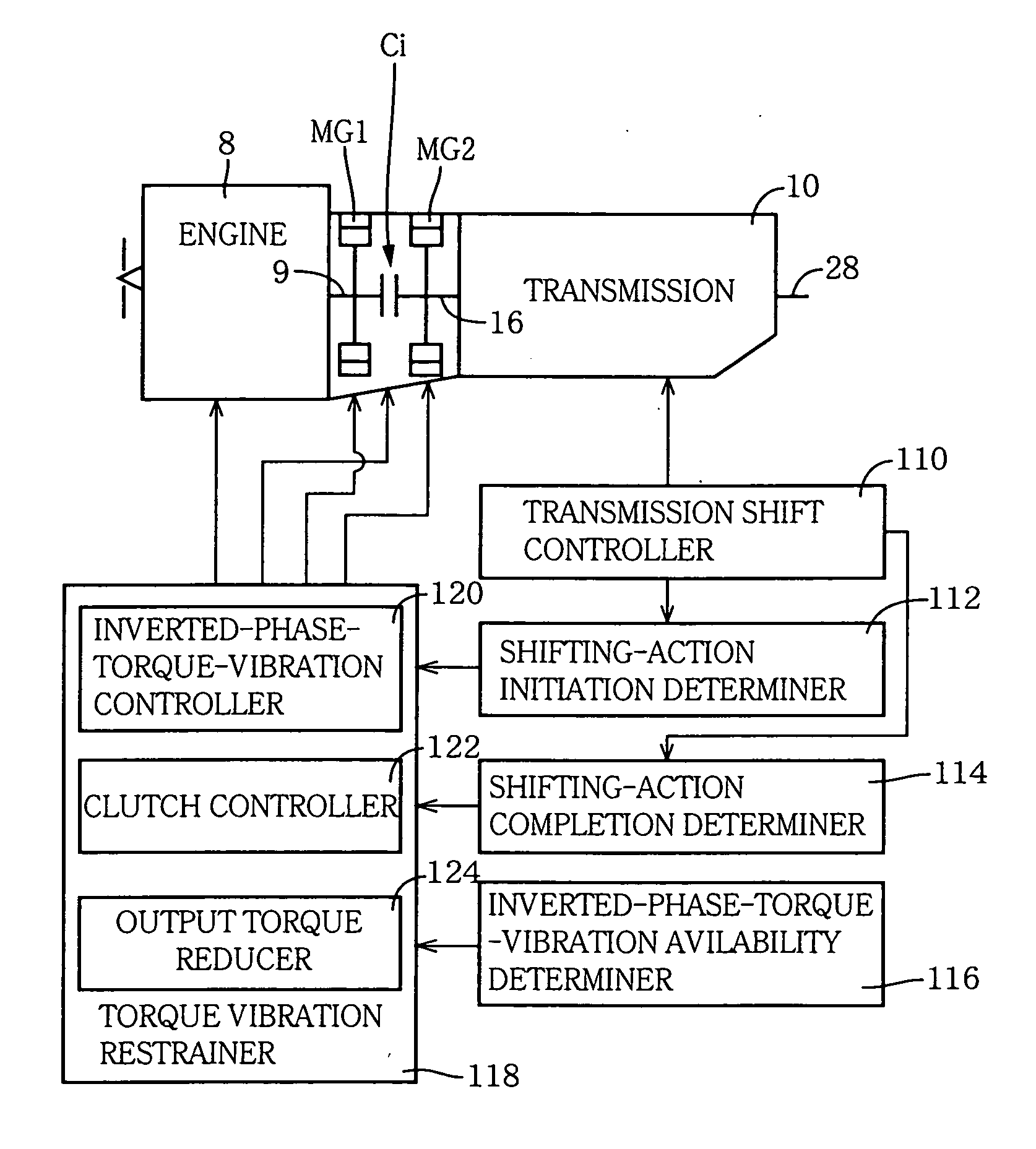
[0081]FIG. 4 is a block diagram showing a control system for controlling the engine 8, clutch Ci, automatic transmission 10 and motor / generators MG1, MG2 (each of which also severs as a drive power source as the engine 8). The control system includes an electronic control unit (ECU) 90 which is constructed according to the invention. The ECU 90 is arranged to receive output signals of various sensors which include an accelerator pedal sensor 51, an engine speed sensor 58, an intake air quantity sensor 60, a throttle sensor 62, a vehicle speed sensor 64, an input shaft speed sensor 66, a brake switch 68, a shift-lever position sensor 74, a coolant water temperature sensor 76, an oil temperature sensor 80, a catalyst temperature sensor 82 and an acceleration sensor 84. The accelerator pedal sensor 51 is provided to detect an operating amount or angle Acc of an accelerator operating member in the form of an accelerator pedal 50 which is to be depressed by the amount corresponding to an...

second embodiment

[0116] In the present second embodiment, the clutch controller 220, the inverted-phase-torque-vibration controller 222 and the output torque reducer 224 cooperate to constitute a torque vibration restrainer. The clutch controller 220 constitutes a primary restraining portion of the torque vibration restrainer, while the inverted-phase-torque-vibration controller 222 and the output torque reducer 224 cooperate to constitute a secondary restraining portion 218 of the torque vibration restrainer. The secondary restraining portion 218 cooperates with the clutch controller 220 as the primary restraining portion, to restrain the torque vibration which is generated in the power transmitting path in a final stage of the shifting action or immediately after the shifting action. Specifically, the secondary restraining portion 218 causes the MG1 or MG2 to generate the inverted-phase torque vibration which is inverted in phase with respect to the generated torque vibration, for offsetting the g...


PUM


Abstract

A control apparatus for controlling a stepped automatic transmission of a vehicle having an output shaft and an input shaft which is to be connected to an engine of the vehicle through a clutch while a shifting action is being effected in the transmission. The control apparatus includes a torque vibration restrainer operable, upon completion of the shifting action in the transmission, to restrain a torque vibration which is generated in a power transmitting path of the vehicle. The torque vibration restrainer applies an inverted-phase torque vibration which is inverted in phase with respect to the generated torque vibration, to the power transmitting path, and / or place the clutch in its slipping state or released state, for restraining the generated torque vibration.

Description

[0001] This application is based on Japanese Patent Applications Nos. 2004-134912 and 2004-134913 filed in Apr. 28, 2004, the content of which is incorporated hereinto by reference. BACKGROUND OF THE INVENTION [0002] 1. Field of the Invention [0003] The present invention relates in general to a control apparatus for controlling a stepped automatic transmission of a vehicle. More particularly, the invention is concerned with a technique for restraining a torque vibration generated immediately after a shifting action of the transmission which is effected while an input shaft of the transmission and an engine of the vehicle are being mechanically connected to each other. [0004] 2. Discussion of Related Art [0005] There is known a vehicle equipped with a stepped automatic transmission having an input shaft that is to be mechanically connected to an engine of the vehicle during a shifting action in which the transmission is shifted to a selected one of a plurality of drive positions (gea...

Claims


Application Information

Patent Timeline
IPC IPC(8): B60K1/02F16H3/66F16H61/14F16H63/40
CPCB60K6/38Y10T477/6418B60L2240/423B60W10/06B60W10/08B60W30/19B60W30/20B60W2710/083F02D41/023F02P5/1504F16H3/126F16H3/663F16H3/666F16H2059/6807F16H2061/6603F16H2200/006F16H2200/0086F16H2200/2007F16H2200/2023F16H2200/2097Y02T10/46Y02T10/623Y02T10/6286Y02T10/642Y10T477/677Y10T477/23Y10T477/26B60K6/44Y02T10/40Y02T10/62Y02T10/64
Inventor TABATA, ATSUSHINOZAKI, KAZUTOSHI
Owner TOYOTA JIDOSHA KK
Learn More