Infrared suppressor apparatus and method

Active Publication Date: 2007-02-08
GENERAL ELECTRIC CO
View PDF6 Cites 22 Cited by
  • Summary
  • Abstract
  • Description
  • Claims
  • Application Information

AI Technical Summary

Benefits of technology

[0006] Some aspects of the present invention therefore provide a method for suppressing infrared radiation from an engine of an aircraft operating in an environment. The method includes directing hot exhaust from the aircraft engine into a lobed mixer of a single baffle infrared supp

Problems solved by technology

Signature reductions reduce the possibility of detection and pursuit by enemy anti-aircraft forces including heat-seeking missiles.
However, even as suppressor construction arrang

Method used


Image

  • Infrared suppressor apparatus and method
  • Infrared suppressor apparatus and method
  • Infrared suppressor apparatus and method

Examples


Embodiment Construction

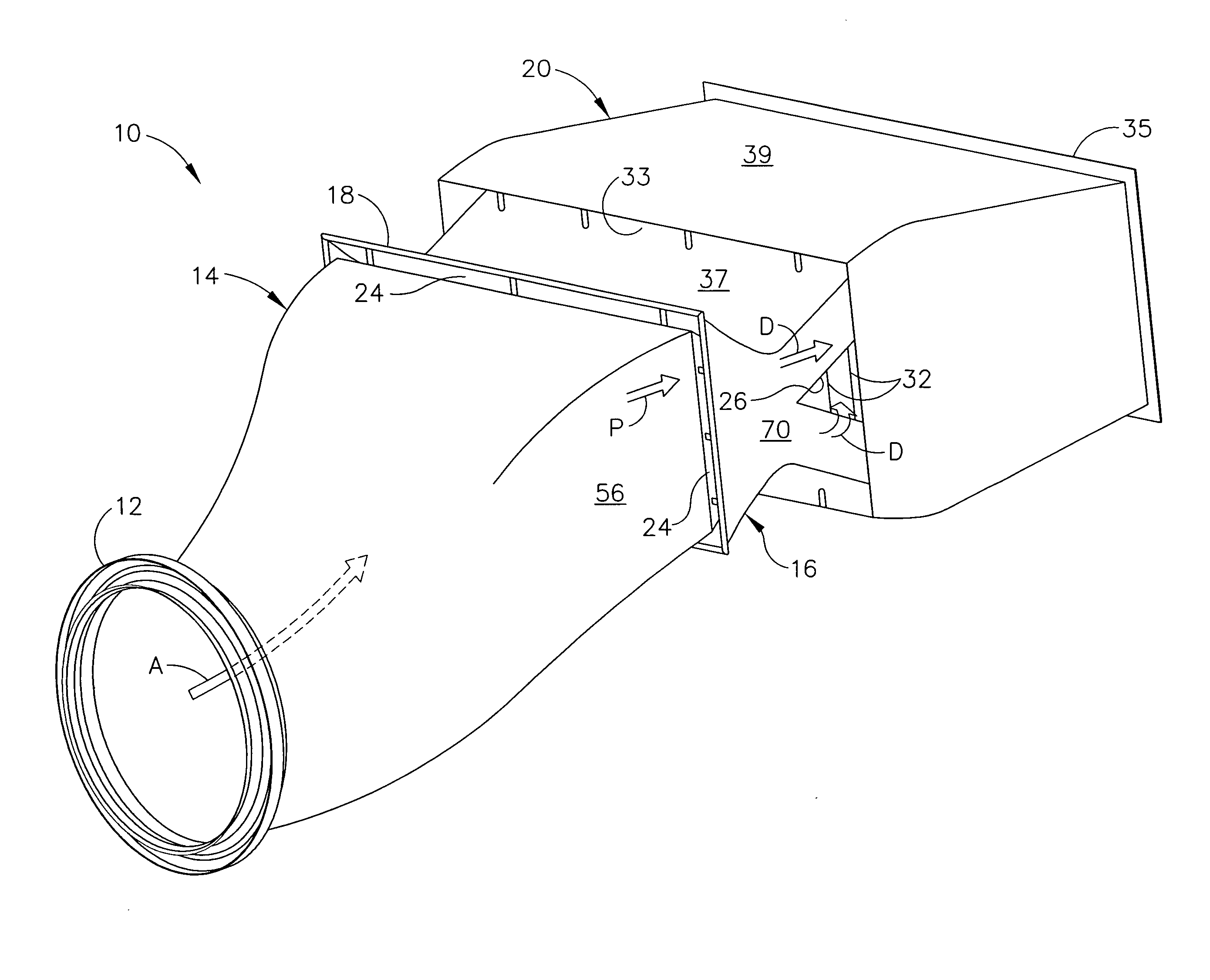
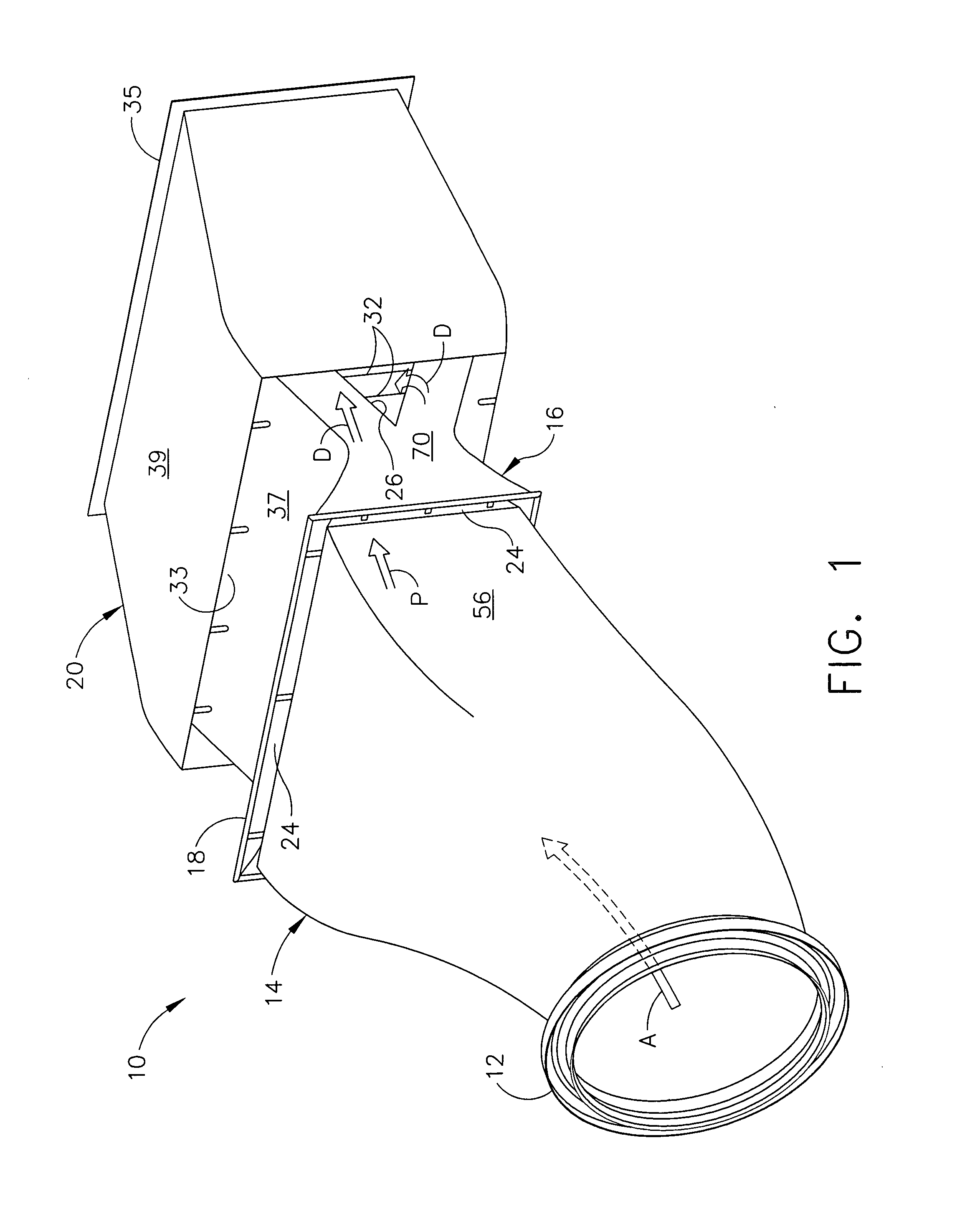
[0035] In some configurations and referring to FIG. 1, an infrared suppressor assembly 10 is fitted to the back end of a standard turboshaft or turboprop engine (not shown). An adapter ring 12 slides over the tailpipe of the turboshaft engine. Adapter ring 12 may comprise a finger seal having a plurality of metal strips (not shown) that fit over a cylindrical section of an engine and hold tight to it. The metal strips are mounted on a slidable and moveable disk, so that if the engine moves relative to suppressor assembly 10, adapter ring 12 takes up the movement. Hot exhaust gas from the jet engine thereby flows into a stage I duct 14 that transitions from a round shape to a rectangular shape in the natural direction of the exhaust flow. In some configurations, stage I duct 14 is straight, however, in other configurations, stage I duct 14 can be repositioned to facilitate guiding the exhaust flows from the engine and away from the aircraft.

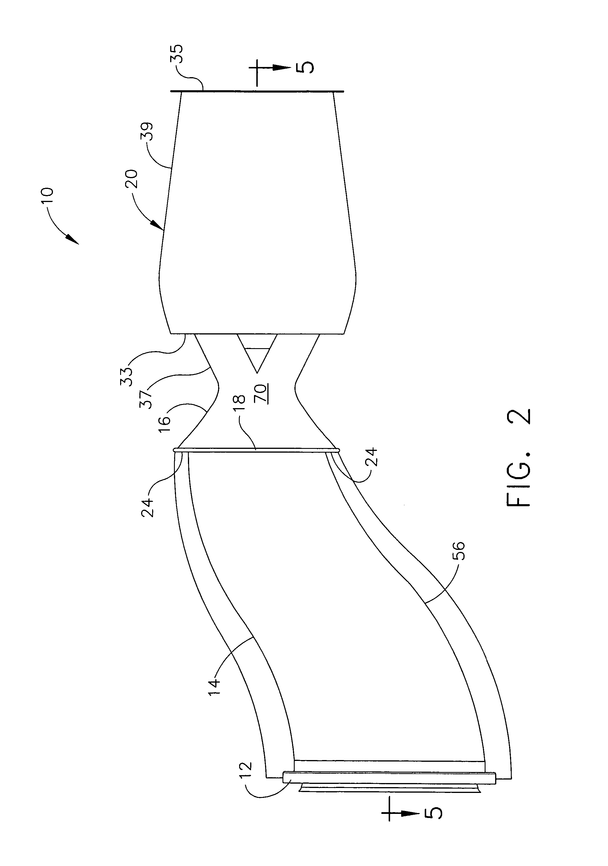
[0036]FIG. 2 is a side elevation view of i...


PUM


Abstract

A method for suppressing infrared radiation from an engine of an aircraft operating in an environment includes directing hot exhaust from the aircraft engine into a lobed mixer of a single baffle infrared suppressor having a collapsible, translatable baffle to generate alternating flows of hot exhaust gas and cold air. The method further includes directing the alternating flows of hot exhaust gas and cold air towards the single baffle assembly to mix the hot exhaust gas with the cold air.

Description

BACKGROUND OF THE INVENTION [0001] This invention relates generally to infrared suppression devices and more generally to methods and apparatus for reducing infrared emission from gas turbines such as those used, for example, in helicopters. [0002] In some helicopters used in hostile environments, gear boxes under helicopter rotors are driven by gas turbine engines. These engines rotate at very high RPM, although the helicopter rotors themselves rotate at low RPM because of their diameter. The tailpipes of the gas turbine engines are exhausted overboard. The tailpipe becomes very hot from this hot exhaust gas and thus provides a very bright infrared signal. [0003] With recent advancements in weapons detection technology, there is growing recognition of the importance of reducing the infrared signature associated with gas turbine engines powering military aircraft and land combat vehicles. Signature reductions reduce the possibility of detection and pursuit by enemy anti-aircraft for...

Claims


Application Information

Patent Timeline
IPC IPC(8): F02K7/00
CPCF02K1/825F02K1/386
Inventor STEYER, WILLIAMKIEFFER, CHRISTOPHER MARLOWTINGLE, WALTER J.
Owner GENERAL ELECTRIC CO
Why Eureka
Try Eureka