Method for operating an axhaust gas treatment device

a gas treatment device and axhaust technology, applied in the direction of exhaust treatment electric control, electrical control, separation process, etc., can solve the problems of internal combustion engine torque jump, possible occurring, reduced to such an extent that regeneration is aborted, etc., to reduce the boost pressure

Inactive Publication Date: 2005-11-03
ROBERT BOSCH GMBH
View PDF7 Cites 3 Cited by
  • Summary
  • Abstract
  • Description
  • Claims
  • Application Information

AI Technical Summary

Benefits of technology

[0006] The procedure of the present invention allows the operative mode change to be made without the possibly occurring torque jump being noticed by the driver.
[0014] It is possible, for example, to retard the timing of a main fuel injection. Alternatively or additionally, provision can be made for at least one post-injection of fuel. Alternatively or additionally, it is possible to drive a throttle valve in the direction of closure. As an alternative, or in addition, it is possible to reduce a boost pressure.

Problems solved by technology

Secondly, a torque jump of the internal combustion engine, possibly occurring when changing the operating mode from normal operation to regeneration, is reduced to such an extent that it is no longer noticed by a driver of a motor vehicle in which the internal combustion engine is used for propulsion.
If the operating state of the internal combustion engine becomes unfavorable during regeneration, the regeneration is aborted.

Method used


Image

  • Method for operating an axhaust gas treatment device
  • Method for operating an axhaust gas treatment device
  • Method for operating an axhaust gas treatment device

Examples


Embodiment Construction

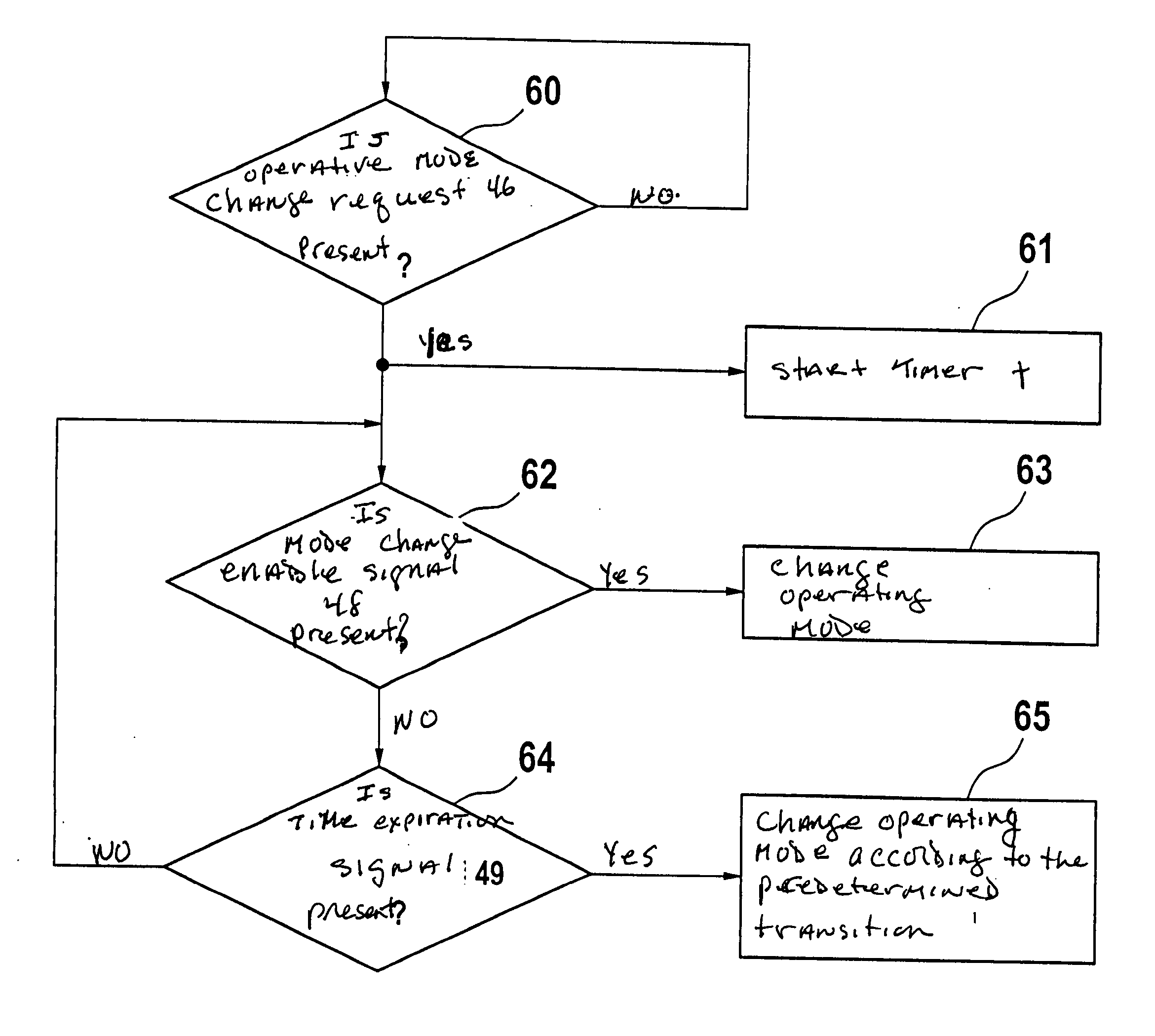
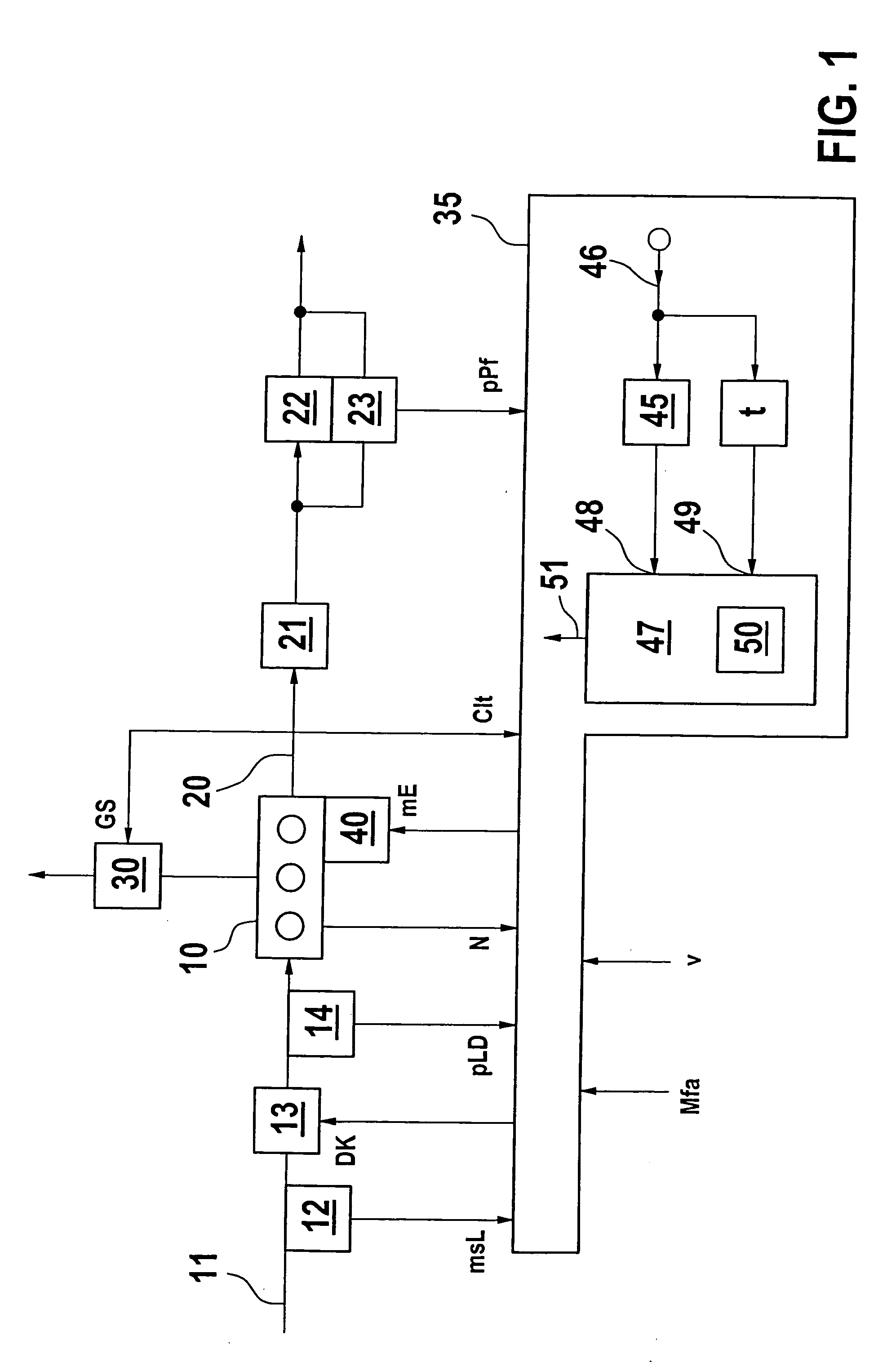
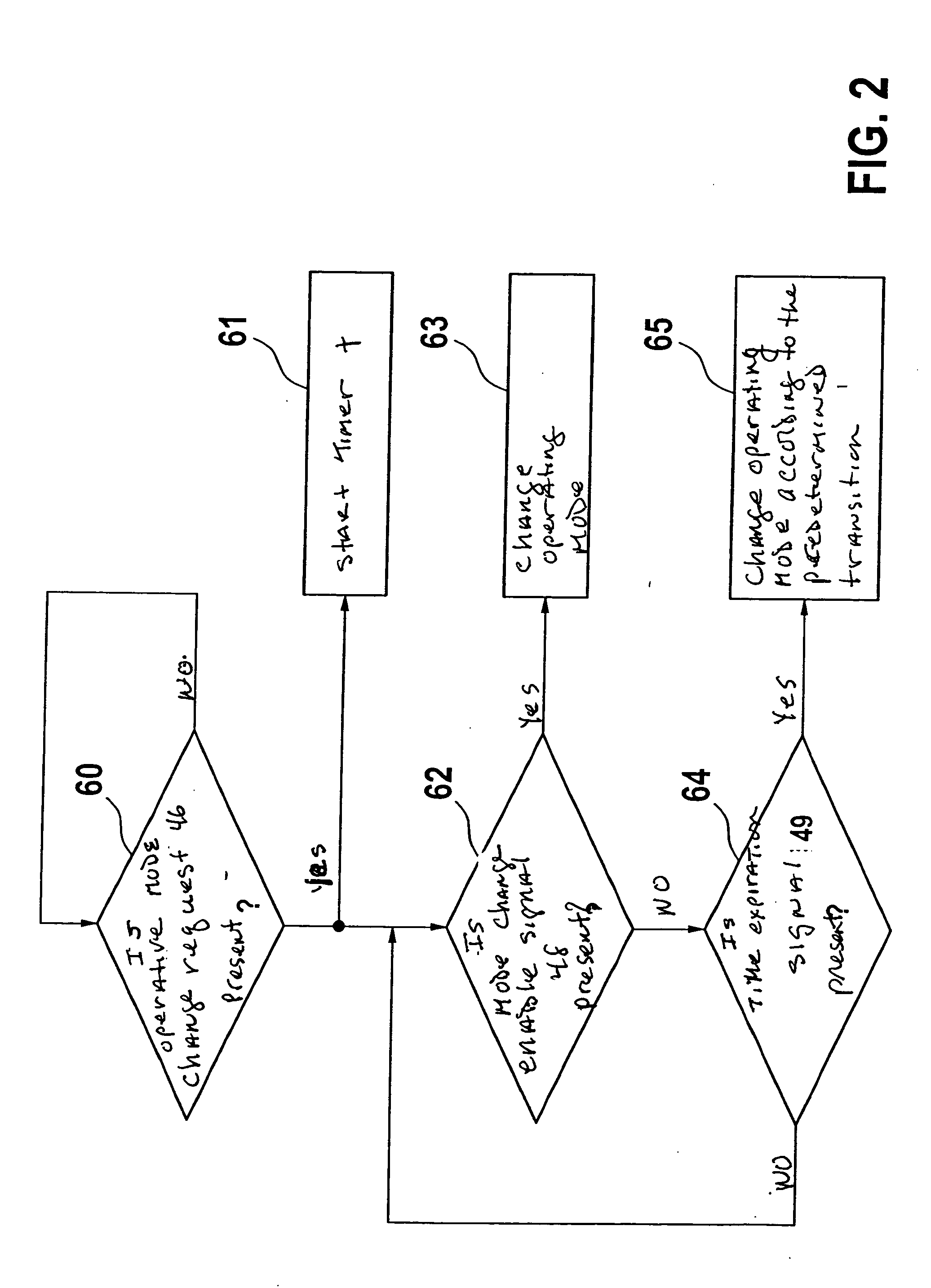
[0017]FIG. 1 shows an internal combustion engine 10 having an intake tract 11 in which are located an air sensor 12, a throttle valve 13 as well as a boost pressure sensor 14.

[0018] Located in an exhaust tract 20 of internal combustion engine 10 is a catalyst 21, a particulate filter 22 as well as a loading pressure sensor 23. Catalyst 21 and particulate filter 22 form an exhaust gas treatment device 24.

[0019] Internal combustion engine 10 is connected to a transmission 30, which is supplied with a transmission control signal GS from a control system 35.

[0020] Control system 35 is provided with an air signal msL from air sensor 12, a boost pressure signal pLD from boost pressure sensor 14, a rotational speed N from internal combustion engine 10, a power transmission signal Clt from transmission 30, and a loading pressure signal pPF from loading pressure sensor 23.

[0021] Moreover, control system 35 is supplied with a desired torque value Mfa and a velocity signal v.

[0022] Contro...


PUM


Abstract

A method for operating an exhaust gas treatment device of an internal combustion engine in which a change in the operating mode of the internal combustion engine is made as a function of a parameter. A timer is started in response to an operative mode change request. During the time period set by the timer, the system continuously decides, based on evaluation of at least one parameter, whether the change in operating mode can be made. If this is the case, the operative mode change is made immediately. If this is not the case, the operative mode change is made no later than when the time period set by the timer has expired. The method ensures that a driver of a motor vehicle in which the internal combustion engine is provided for propulsion will not notice a torque jump of the internal combustion engine, possibly occurring during an operative mode change.

Description

BACKGROUND INFORMATION [0001] A method is described in German Patent Application No. DE 100 56 016, in which a regeneration is initiated as a function of a parameter of an exhaust gas treatment device. The temperature of the exhaust gas treatment device during regeneration depends, first of all, on the state of the exhaust gas treatment device and, secondly, on the operating state of the internal combustion engine. The regeneration of the exhaust gas treatment device is carried out, for example, by introducing unburned fuel into the exhaust tract of the internal combustion engine. The fuel reacts exothermically in an oxidation catalyst. The heated exhaust gases heat the exhaust gas treatment device to the starting temperature required for regeneration. The regeneration is divided into two phases. In the first phase, the quantity of unburned fuel in the exhaust gas increases in the course of time. In the second phase, the amount of unburned fuel is kept at least approximately constan...

Claims


Application Information

Patent Timeline
Patent Type & Authority Applications(United States)
IPC IPC(8): B01D53/86F02D9/02F01N3/02F01N3/023F01N3/20F01N3/24F01N9/00F02D29/00F02D41/02F02D41/04F02D41/12F02D41/30F02D41/34F02D43/00
CPCF02D41/023F02D41/027Y10T477/68F02D41/3064F02D41/123
Inventor PFAEFFLE, ANDREASKOLITSCH, MICHAELSCHAFFRATH, ANDREAS
Owner ROBERT BOSCH GMBH
Why Eureka
Try Eureka