Bipolar resectoscope electrode

a resectoscope and bipolar technology, applied in the field of resectoscopes, can solve the problems of difficult mate between tungsten and brass or other contact metals, and achieve the effect of safe and reliable operation and flexibleness

Active Publication Date: 2005-11-03
GYRUS ACMI INC (D B A OLYMPUS SURGICAL TECH AMERICA)
View PDF18 Cites 14 Cited by
  • Summary
  • Abstract
  • Description
  • Claims
  • Application Information

AI Technical Summary

Benefits of technology

[0010] The present invention overcomes the deficiencies of prior art devices by providing

Problems solved by technology

Tungsten is difficult to mate with brass or other contact metals becau

Method used


Image

  • Bipolar resectoscope electrode
  • Bipolar resectoscope electrode

Examples


Embodiment Construction

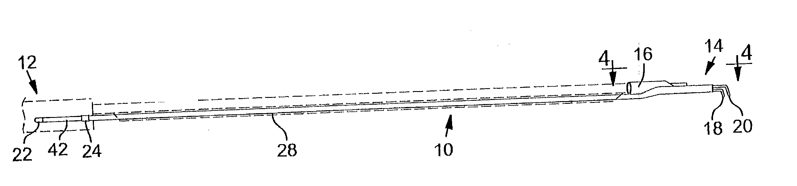
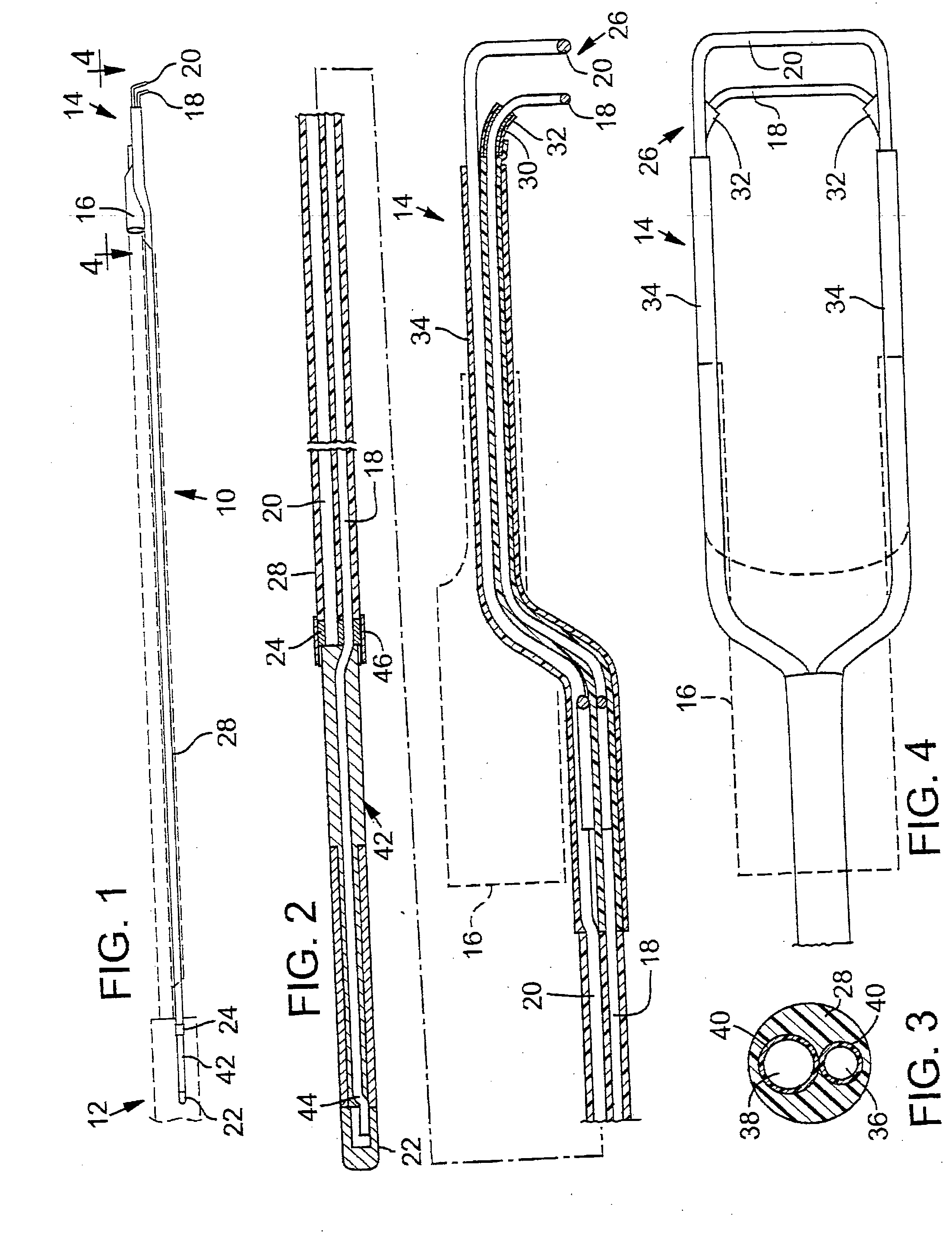
[0024] Representative embodiments of the present invention are shown in FIGS. 1-4, wherein similar features share common reference numerals.

[0025]FIG. 1 shows a preferred embodiment of an electrode assembly 10 for an electrosurgical resectoscope. Electrode assembly 10 includes a proximal portion 12 and a distal portion 14. Proximal portion 12 is adapted to be received in a jack on a conventional electrosurgical resectoscope (shown in phantom) to apply electrical energy to the body of a patient for tissue ablation and coagulation, for example. Electrode 10 includes a connector element 16 for connection with the resectoscope in a known manner. A power element 18 and a return element 20 are introduced together into the body. Power element 18 and return element 20 are engageable with and insertable into the body tissue. Electrical energy is applied to the body through power element 18 that receives power through a conductive power contact 22 from a power source (not shown). Electrical ...


PUM


Abstract

An electrode assembly is provided having an active power element and a current return element extending through a flexible multilumen tube to be electrically insulated from each other. The active power element extends through the multilumen tube and terminates in a “J-hook” and is connected to a conductive power contact through a constructed form fit. The return element extends through the multilumen tube and directly connects to a power return contact, thus eliminating any joints in the electrical path.

Description

BACKGROUND OF THE INVENTION [0001] This invention is directed to resectoscopes and, more particularly, to an improved electrode assembly for use with resectoscopes. Such electrodes may be monopolar or bipolar. Monopolar probes include a single active electrode introduced into a body cavity to be engageable with and insertable into a tissue portion of the body cavity. A passive electrode is attached to the outer body surface of the patient and a conducting plate is typically adhesively attached to the patient's leg. The patient's body serves to complete the electrical circuit. Tissue ablation and coagulation is achieved by introducing sufficient power into the active electrode. Bipolar electrode probes include both active and passive electrodes that are similarly introduced together into the body cavity and are spaced apart from each other by a predetermined distance. Each electrode is engageable with and insertable into the tissue portion. The electrical circuit is completed by the ...

Claims


Application Information

Patent Timeline
IPC IPC(8): A61B18/14A61B18/12H01R43/00
CPCA61B18/149
Inventor SNAY, JAMES P.BLAISDELL, MICHAEL D.
Owner GYRUS ACMI INC (D B A OLYMPUS SURGICAL TECH AMERICA)
Why Eureka
Try Eureka