Lancet depth adjustment assembly

a technology of depth adjustment and assembly, which is applied in the field of lancet depth adjustment assembly, can solve the problems of excessive bleeding and/or a substantial amount of pain, and the standard depth at which the piercing tip protrudes may not be ideal,

Inactive Publication Date: 2005-11-03
SCHRAGA STEVEN
View PDF21 Cites 101 Cited by
  • Summary
  • Abstract
  • Description
  • Claims
  • Application Information

AI Technical Summary

Benefits of technology

[0013] The depth adjustment element is thereby structured to define a spacing between the patient's finger and the piercing aperture, and in turn define a depth to which the piercing tip can penetrate the finger. For example, as the piercing tip is generally configured to pass a predefined distance through the piercing aperture of the housing, a larger spacing between the finger and the piercing aperture, as defined by the depth adjustment element, reduces the depth to which the piercing tip ultimately penetrates the finger.

Problems solved by technology

Moreover, as a result of the increasing popularity of blood testing procedures, especially by individual patients, the field of art associated with lancet devices is quite crowded, with a variety of often complex and intricate structures being utilized to drive the piercing tip of the lancet into the flesh of a patent.
Unfortunately, with some types of lancets, some patients and / or depending upon the circumstance, the standard depth which the piercing tip protrudes may not be ideal.
Conversely, however, some patients, either at all times or at selective times depending upon their condition, are very sensitive and excessive penetration can lead to excessive bleeding and / or a substantially amount of pain.
As a result, in such patients a standard, maximum depth is generally undesirable.
Unfortunately, however, the increased penetration that results from the longer, thinner lancets, tends to be more painful and may therefore be excessive for some patients.
(Of course, such multi-patient use of a lancet device is never recommended.)

Method used


Image

  • Lancet depth adjustment assembly
  • Lancet depth adjustment assembly

Examples


Embodiment Construction

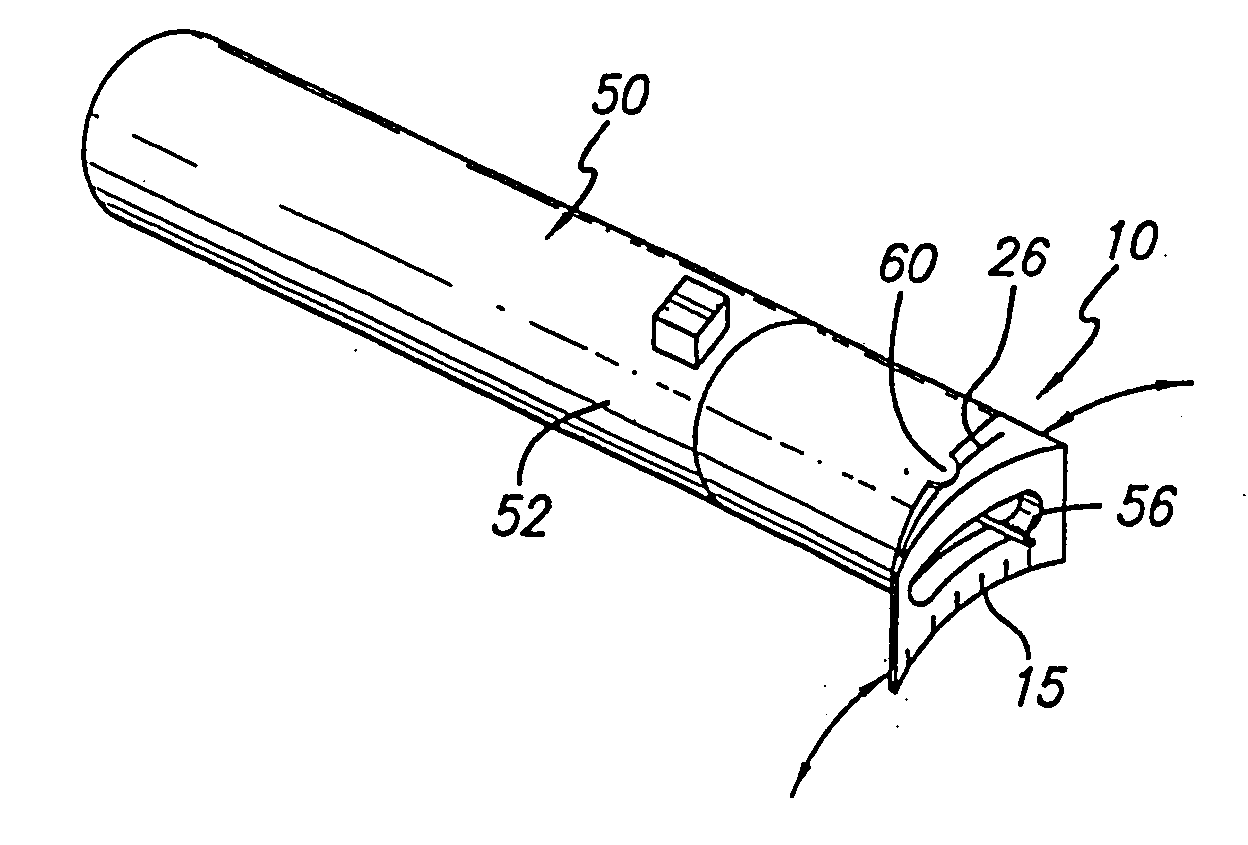
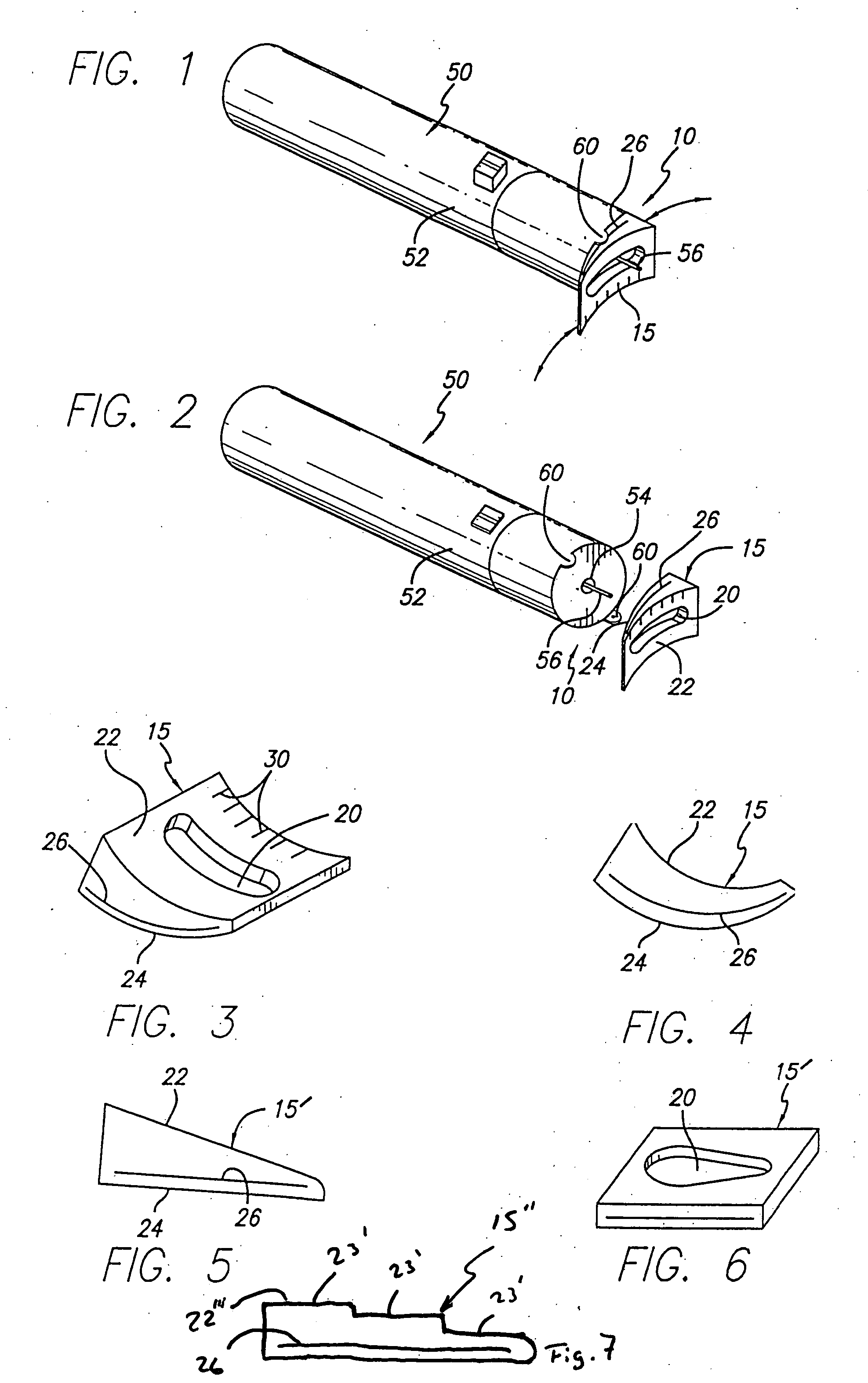
[0025] Shown throughout the Figures, the present invention is directed towards a lancet depth adjustment assembly, generally indicated as 10. The depth adjustment assembly 10 is preferably structured for use in conjunction with a lancet device 50, that is normally used to fire a lancet into a patient's skin, such as at a patient's finger or earlobe, so as to allow a blood sample to be generated and collected. (Although the present invention can be used when piercing any portion of a patient's body, for purposes of clarity only, the following description is made primarily with reference to the piercing of a finger.) Although, there are a variety of different types and configurations of lancet devices 50 which may be utilized with the lancet depth adjustment assembly 10 of the present invention, preferably the lancet device 50 is of the type which includes a housing 52 that contains a lancet with a piercing tip 56 movably disposed therein. Moreover, the lancet device 50 is also prefer...


PUM


Abstract

A lancet depth adjustment assembly structured to be used use with a lancet device of the type including a lancet disposed movably within a housing so as to pass into a piercing orientation wherein a piercing tip of the lancet protrudes from a piercing aperture defined in the housing. The lancet depth adjustment assembly includes a depth adjustment element movably secured in overlying relation to the piercing aperture of the housing and having a piercing access including one or more openings structured to permit passage of the piercing tip of the lancet therethrough. The depth adjustment element is structured to be interposed between a finger of a patient and the piercing aperture so as to define a spacing therebetween, and accordingly define a depth to which the piercing tip, which protrudes a defined amount from the housing, penetrates the body part. Furthermore, the depth adjustment element is constructed of a varying thickness so as to vary the spacing between the body part and the piercing aperture in accordance with a thickness of a portion of the depth adjustment element disposed in overlying relation to the piercing aperture at a time of operation of the lancet device.

Description

CLAIM OF PRIORITY [0001] The present is a continuation of U.S. patent application Ser. No. 09 / 995,411, filed Nov. 27, 2001, which is issuing as U.S. Pat. No. 6,887,253 on May 3, 2005, which is a continuation of U.S. patent application Ser. No. 09 / 477,950, filed Jan. 5, 2000, which is issuing as U.S. Pat. No. 6,322,575 on Nov. 27, 2001, the contents of which are hereby incorporated by reference.BACKGROUND OF THE INVENTION [0002] 1. Field of the Invention [0003] The present invention relates to a lancet depth adjustment assembly structured to be interposed between a body part to be pierced, such as a patient's finger or earlobe, and a piercing aperture of a lancet device housing, so as to effectively define and vary a depth to which a piercing tip of the lancet is able to penetrate the patient's body part disposed thereon. As such a patient can effectively select and define a sensitivity level that corresponds their particular needs and circumstance in a substantially easy to use mann...

Claims


Application Information

Patent Timeline
Patent Type & Authority Applications(United States)
IPC IPC(8): A61B5/15A61B17/32A61B19/00
CPCA61B5/1411A61B2019/303A61B5/150022A61B5/15186A61B5/150412A61B5/15113A61B5/150183A61B5/150503A61B2090/033
Inventor SCHRAGA, STEVEN
Owner SCHRAGA STEVEN
Why Eureka
Try Eureka