Implantable lenses with modified edge regions

a technology of edge region and implantable lens, which is applied in the field of implantable lenses, can solve the problems of corneal haze, undesirable condition, vision impairment, etc., and achieve the effect of less permeability and same permeability

a technology of edge region and implantable lens, which is applied in the field of implantable lenses, can solve the problems of corneal haze, undesirable condition, vision impairment, etc., and achieve the effect of less permeability and same permeability

US20050246016A1Inactive Publication Date: 2005-11-03REVISION OPTICS

Image

  • Implantable lenses with modified edge regions
  • Implantable lenses with modified edge regions
  • Implantable lenses with modified edge regions

Examples


Embodiment Construction

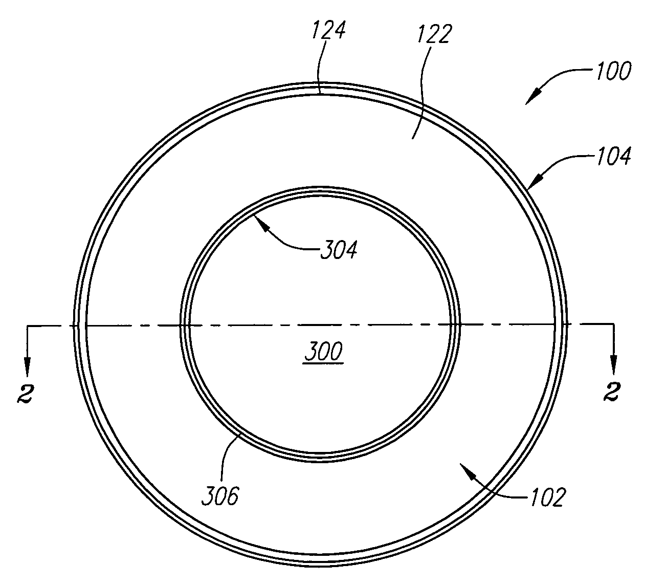
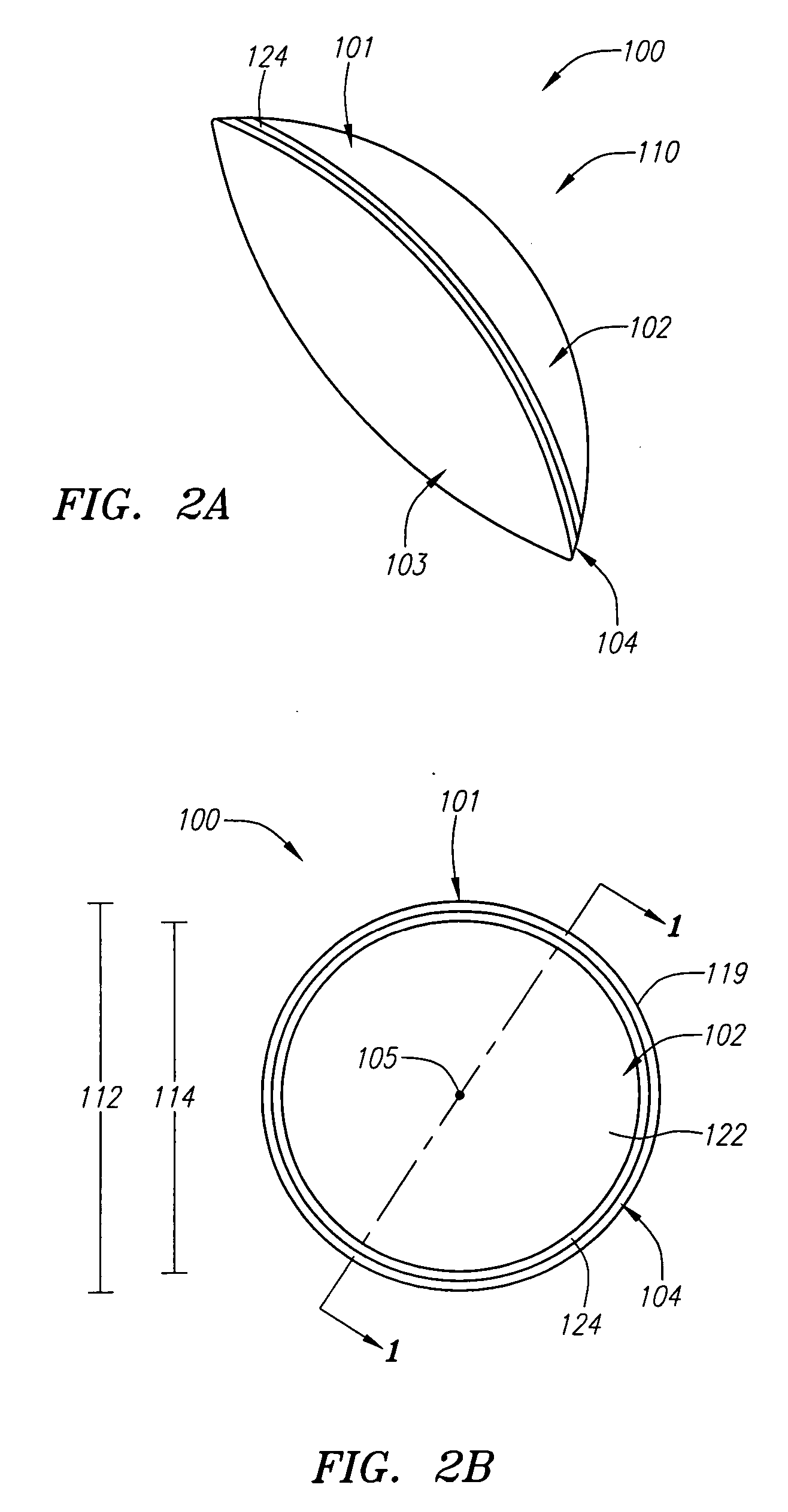
[0030] Described herein are improved implantable lenses with modified edge regions that can reduce stimulation of adverse tissue reactions in proximity to the lens. FIGS. 2A-E depict various views of an example embodiment of implantable lens 100. FIG. 2A is a perspective view depicting implantable lens 100, where lens 100 has lens body 101, anterior surface 102, posterior surface 103 and outer edge surface 104. FIG. 2B is a top-down view of lens 100 taken in direction 110. Here it can be seen that lens body 101 has a generally circular outer profile 119 with central apex 105 representing the most anterior point of anterior surface 102. Diameter 112 represents the overall diameter of lens body 101 and diameter 114 represents the diameter of corrective portion 122, which is the portion of anterior surface 102 configured to provide correction for one or more specific visual impairments.

[0031]FIG. 2C is a cross-sectional view of lens 100 taken along line 1-1 of FIG. 2B. From this view ...


PUM

PropertyMeasurementUnit
thicknessaaaaaaaaaa
diameteraaaaaaaaaa
thicknessaaaaaaaaaa

Abstract

The implantable lenses described herein provide for modified edge regions. In one example embodiment an implantable lens includes an anterior surface, a posterior surface and an outer edge surface separating the anterior and posterior surfaces. The anterior surface can include a corrective portion and a beveled portion. The beveled portion can be located between the corrective portion and the outer edge surface. The outer edge surface can have a first portion and a second portion, where the first portion abuts the posterior surface and the second portion, and where the second portion further abuts the beveled portion. The modified edge region provides a more gradual transition between the anterior and posterior surfaces.

Description

CROSS-REFERENCE TO RELATED APPLICATIONS [0001] This application is a continuation-in-part of U.S. patent application Ser. No. 10 / 837,402, entitled “Aspherical Corneal Implant” and filed Apr. 30, 2004, which is fully incorporated herein by reference.FIELD OF THE INVENTION [0002] The field of the invention relates generally to implantable lenses and, more particularly, to implantable lenses having modified edge regions. BACKGROUND INFORMATION [0003] As is well known, abnormalities in the human eye can lead to vision impairment. Some typical abnormalities include variations in the shape of the eye, which can lead to myopia (near-sightedness), hyperopia (far-sightedness) and astigmatism as well as variations in the tissue present throughout the eye, such as a reduction in the elasticity of the lens, which can lead to presbyopia. Certain devices, generally referred to as implantable lenses, have been used to successfully treat these and other types of vision impairment. [0004] Implantabl...

Claims


Application Information

Patent Timeline
03 Nov 2005
Publication
US20050246016A1
IPC
A61F2/14
CPC
A61F2/14; B29D11/023; B29D11/00028; A61F2/147; A61F2/16; G02C7/02
Inventors
MILLER, TROY A.; CUNANAN, CRYSTAL M.