Hydraulic Geofracture Energy Storage System with Desalination

a geofracture and energy storage technology, applied in the direction of quary waste water treatment, borehole/well accessories, treatment water, etc., can solve the problems of grid instability, low capital expenditure and operating costs, and limited renewable electric power at the grid level, not only by source economics, but also by grid stabilization technologies. , to achieve the effect of less permeability and increased propagation pressure of the fractur

Inactive Publication Date: 2017-03-30
QUIDNET ENERGY INC
View PDF0 Cites 0 Cited by
  • Summary
  • Abstract
  • Description
  • Claims
  • Application Information

AI Technical Summary

Benefits of technology

[0014]The present invention uses wells to store fluid at high pressure in fractures (e.g., hydraulic fractures and / or naturally occurring fractures) in the earth. The fluid is used in conventional equipment to produce power as the fluid is produced back from the well. The walls of the fracture may be made less permeable and the propagation pressure of the fracture may be increased by injecting a resin, such as epoxy, into the fracture. The storage capabilities, capital requirements and anticipated rates of return that enable a profitable operation for distributed resources and load management, as well as overnight arbitrage of wind power, are described. If the stored fluid is saline water, such as water produced from strata in the earth, and there is demand for fresh water, a selected fraction of the saline water produced from the storage capacity may be directed to a reverse osmosis unit for desalination.

Problems solved by technology

Neither of these is cost-competitive today without substantial publicly-funded subsidies, although capital expenditures and operating costs are expected to drop over time, and may eventually reach price-parity with coal- and gas-fired power plants.
Output fluctuations also cause grid instability; without dynamic load-leveling means (e.g. smart grid technologies) renewable power sources must now be limited to less than about ten percent of delivered power on a given electric grid.
As a result, renewable electric power at the grid level is limited not only by source economics, but also grid stabilization technologies.
Plainly, current battery technology is prohibitively expensive for general grid-scale storage, even with reasonable technical improvements and economies of scale.
Since compression and expansion of air generates large temperature changes, CAES plant to deal with this parasitic energy channel is relatively complex and expensive.
This is simultaneously a period of low productivity for wind turbines, unfortunately.
In many areas, there is also a shortage of fresh or potable water.

Method used


Image

  • Hydraulic Geofracture Energy Storage System with Desalination
  • Hydraulic Geofracture Energy Storage System with Desalination
  • Hydraulic Geofracture Energy Storage System with Desalination

Examples


example 1

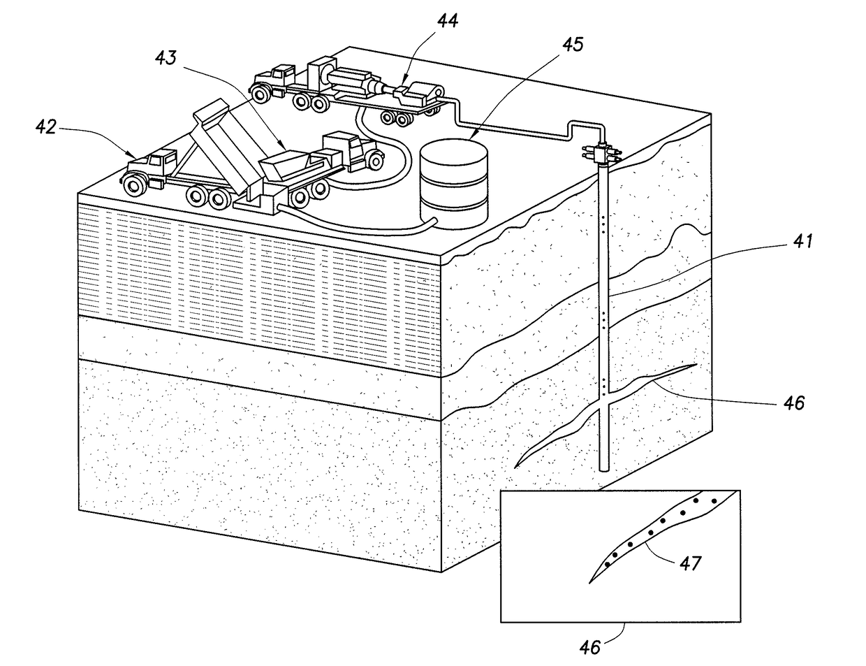
1 km Deep Well, with 1 cm Average Lift Over 100 Meter Radius (Typical Oilfield Frac)

[0031]Well depth: 1,000 m[0032]Fracture radius: 100 m[0033]Slug volume: 31,400,000 m3 [0034]Rock density: 2,800 kg / m3 [0035]Slug mass: 87,900,000,000 kg[0036]Slug weight: 862,000,000,000 Newtons[0037]Average lift: 1 cm[0038]Lift energy: 8,620,000,000 Joules 8.6 E 9 Joules[0039]Storage capacity: 2,395 kw-hr

example 2

1 km Deep Well, with 10 cm Average Lift Over 500 Meter Radius

[0040]Well depth: 1,000 m[0041]Fracture radius: 500 m[0042]Slug volume: 7.85 E 8 m3 [0043]Rock density: 2,800 kg / m3 [0044]Slug mass: 2.20 E 12 kg[0045]Slug weight: 2.16 E 13 Newtons[0046]Average lift: 10 cm[0047]Lift energy: 2.16 E 12 Joule[0048]Storage capacity: 5.99 E 5 kw-hr

[0049]Although explanations of hydraulic fracture properties are described, Applicant does not wish to be bound by a particular scientific theory concerning the properties of hydraulic fractures.

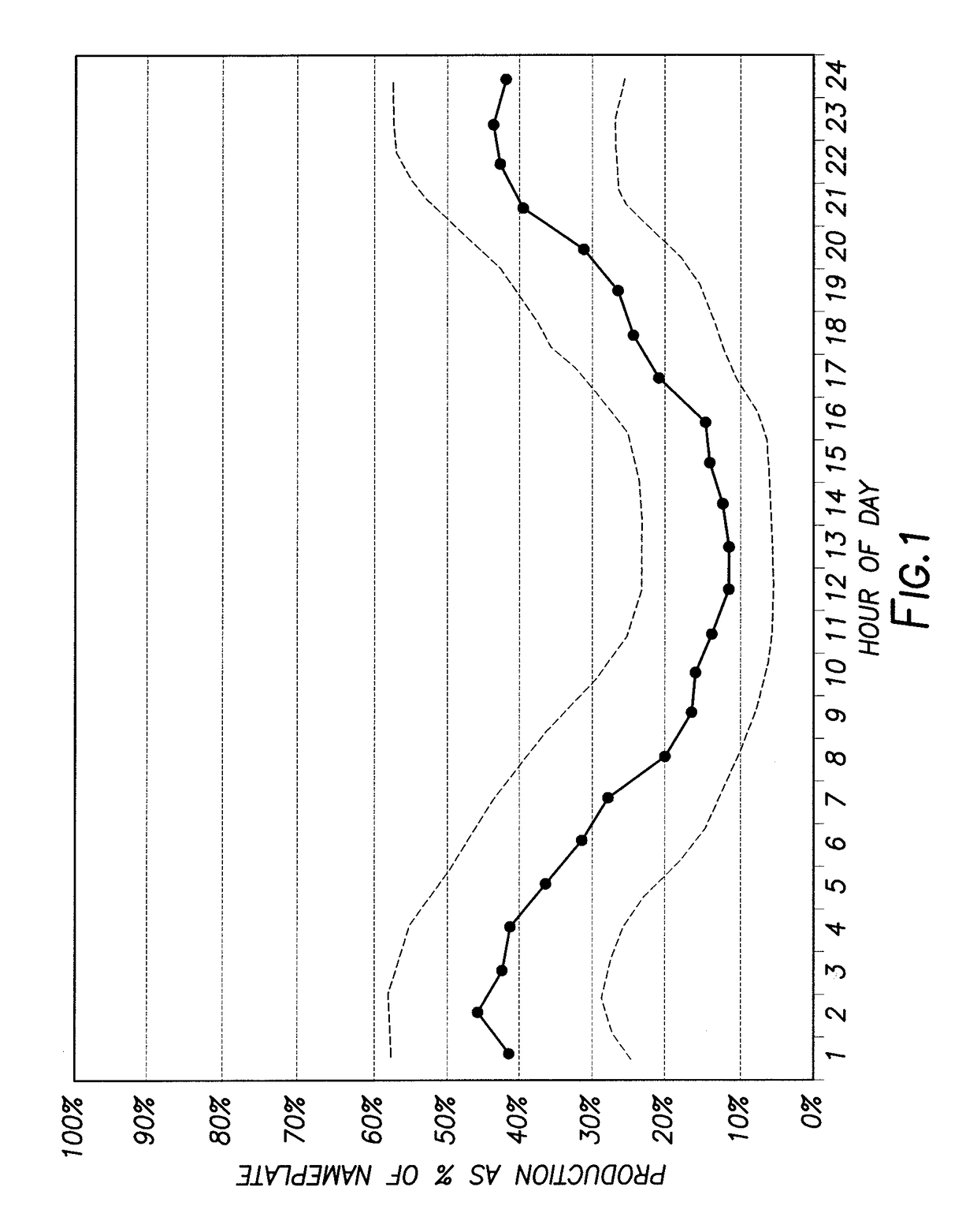
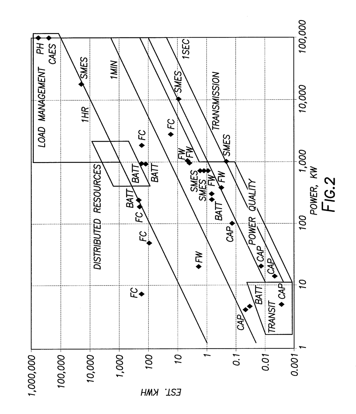
[0050]For comparison, a 3 MW wind turbine operating at typical 30% utilization factor generates 2.16E4 kw-hr per day. The unit described in example 2 can therefore store the entire nominal daily output of wind farm comprised of 167 turbines. If one purchased a battery based storage system for this amount of stored energy at current prices ($400 / kw-hr), a capital investment of roughly $239 Million would be required. We expect that the capital investment for en...


PUM


Abstract

Energy may be stored by injecting fluid into a fracture in the earth and producing the fluid back while recovering power and/or desalinating water. The method may be particularly adapted to storage of large amounts of energy such as in grid-scale electric energy systems. The fracture may be formed and treated with resin so as to limit fluid loss and to increase propagation pressure. The fluid may be water containing a dissolved salt or fresh water and a portion or all of the water may be desalinated using pressure in the water when it is produced.

Description

[0001]This Continuation-in-Part Application claims priority to Ser. No. 14 / 318,742 filed on Jun. 30, 2014, which claims priority to U.S. Non-Provisional Application Ser. No. 12 / 853,066 filed on Aug. 9, 2010, which claims priority to U.S. Provisional Application Ser. No. 61 / 232,625 filed Aug. 10, 2009, all of which are hereby incorporated by reference in their entirety.BACKGROUND OF INVENTION[0002]1. Field of the Invention[0003]This invention relates to energy storage and water desalination. More particularly, fluid is injected down a well to form a hydraulic fracture. Fluid may be pumped into the fracture under pressure and later produced from the fracture under pressure and used to generate power or flow into a reverse osmosis unit for desalination.[0004]2. Discussion of Related Art[0005]A number of factors including energy security, price volatility, carbon regulation, tax incentives and fears of anthropogenic global warming are driving rapid growth of renewable energy sources. Si...

Claims


Application Information

Patent Timeline
Patent Type & Authority Applications(United States)
IPC IPC(8): E21B41/00E21B33/138
CPCE21B33/138E21B41/0085Y02E10/72C02F2307/00B65G5/00F03B13/06F02C6/16H02K7/1807C02F2103/023C02F2103/06C02F2103/08C02F2103/10C02F2303/10F05D2300/607Y02W10/33Y02W10/30Y02W10/37Y02P90/50F03D9/17Y02A20/131Y02A20/141C02F1/441Y02E10/20Y02E60/16Y02E70/30
Inventor SCHMIDT, HOWARD K.MANDELL, AARON H.
Owner QUIDNET ENERGY INC
Why Eureka
Try Eureka