High-pressure tank and method for manufacturing high-pressure tank

a high-pressure tank and manufacturing method technology, applied in the direction of electrochemical generators, container discharging methods, vessel construction details, etc., can solve the problems of liner deterioration, water condensation in storage space, water not being sufficiently removed from storage space, etc., to reduce gas passage and reduce gas leakage

Active Publication Date: 2022-07-28
TOYOTA JIDOSHA KK
View PDF5 Cites 1 Cited by
  • Summary
  • Abstract
  • Description
  • Claims
  • Application Information

AI Technical Summary

Benefits of technology

This patent describes a high-pressure tank with a resin layer that prevents water from entering and causing damage to the tank. The resin layer is designed to be less permeable to gas than the reinforcing layer, reducing gas leakage and improving the tank's stability. Additionally, the tank has reinforcing layers that prevent gas from leaking between the cylinder member and the dome members. This method for manufacturing the tank results in reduced water damage and offers more material options for the resin layer. Overall, this patent provides a solution for creating high-pressure tank with improved durability and stability.

Problems solved by technology

However, the water is sometimes not sufficiently removed from the storage space after the test, and the water that has not been removed may remain in the storage space.
Moreover, when a high-pressure tank is in use, water sometimes condenses in the storage space due to changes in temperature.
Depending on the material of the liner (resin layer), the liner may be deteriorated by the water.
The gas in the storage space is more likely to leak through the fitting portions in which the dome members are fitted on the cylinder member.

Method used


Image

  • High-pressure tank and method for manufacturing high-pressure tank
  • High-pressure tank and method for manufacturing high-pressure tank
  • High-pressure tank and method for manufacturing high-pressure tank

Examples


Embodiment Construction

[0033]Hereinafter, an embodiment according to the present disclosure and a modification thereof will be described with reference to FIGS. 1 to 15.

1. High-Pressure Tank 1

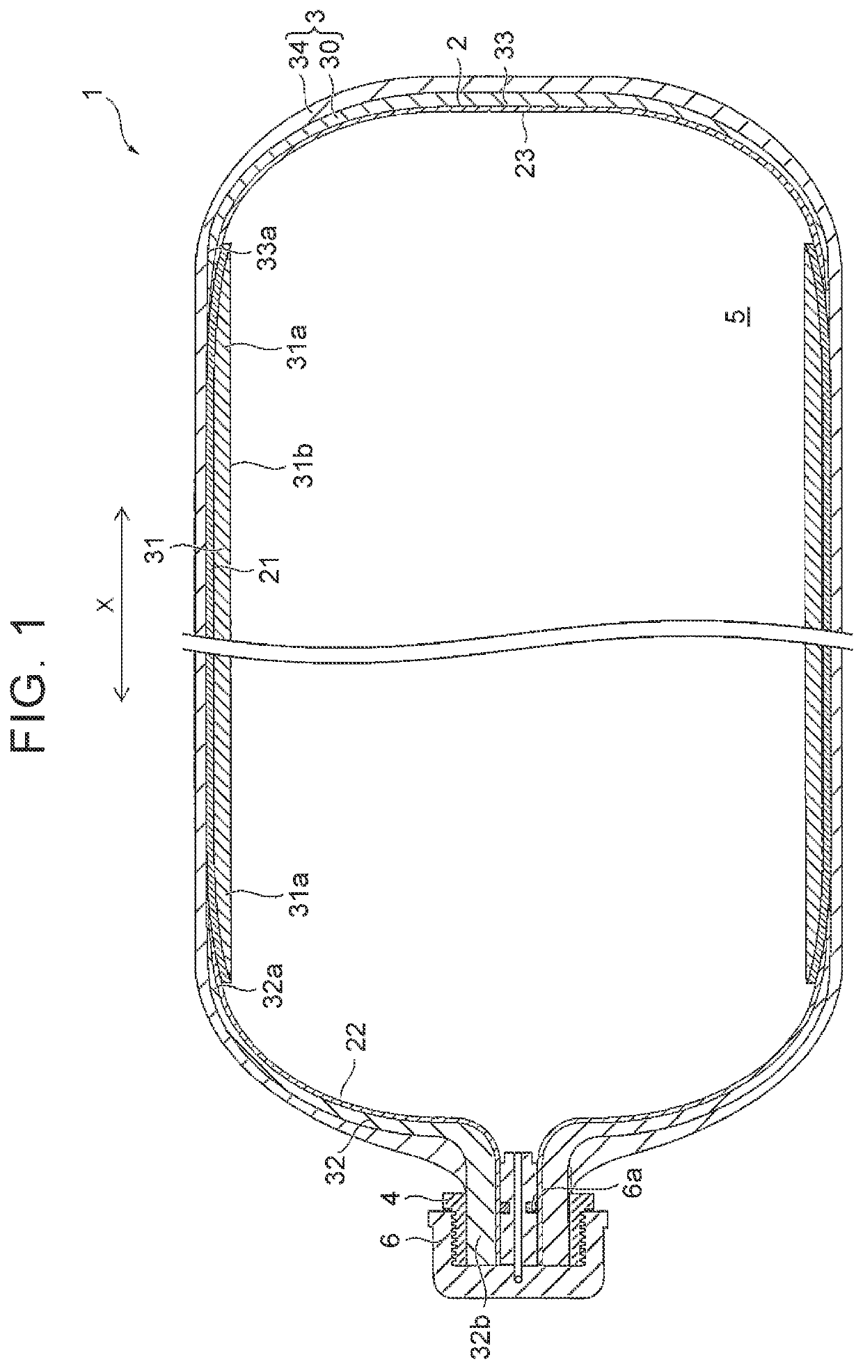
[0034]A high-pressure tank 1 is herein described as a tank that is mounted on a fuel cell vehicle and that is filled with high-pressure hydrogen gas. However, the high-pressure tank 1 can also be applied to other uses. The gas that can be used for the high-pressure tank 1 is not limited to high-pressure hydrogen gas. Examples of the gas that can be used for the high-pressure tank 1 include various compressed gases such as compressed natural gas (CNG), various liquefied gases such as liquefied natural gas (LNG) and liquefied petroleum gas (LPG), and other gases.

[0035]As shown in FIG. 1, the high-pressure tank 1 is a generally cylindrical high-pressure gas storage container with dome-shaped rounded ends. The high-pressure tank 1 includes a gas barrier portion 2 having gas barrier properties and a reinforcing portion 3 ...


PUM

PropertyMeasurementUnit
Thicknessaaaaaaaaaa
Pressureaaaaaaaaaa

Abstract

A high-pressure tank includes a first reinforcing layer and a second reinforcing layer. The first reinforcing layer is a layer obtained by joining dome members to respective end portions of a cylinder member, the dome members being a pair, and an inner peripheral surface of the cylinder member is exposed to a storage space that stores gas. A first resin layer covers the cylinder member between the first reinforcing layer and the second reinforcing layer. The first resin layer is less permeable to the gas in a thickness direction than the first reinforcing layer.

Description

CROSS-REFERENCE TO RELATED APPLICATION[0001]This application claims priority to Japanese Patent Application No. 2021-010390 filed on Jan. 26, 2021, incorporated herein by reference in its entirety.BACKGROUND1. Technical Field[0002]The disclosure relates to a high-pressure tank and method for manufacturing a high-pressure tank.2. Description of Related Art[0003]For example, a high-pressure tank storing fuel gas is used in natural gas vehicles, fuel cell vehicles, etc. This type of high-pressure tank has a reinforcing layer made of a fiber reinforced resin and a storage space that stores gas.[0004]For example, Japanese Unexamined Patent Application Publication No. 2012-149739 (JP 2012-149739 A) proposes, as such a high-pressure tank, a high-pressure tank having a first reinforcing layer made of a fiber reinforced resin and formed on the outer surface of a liner and a second reinforcing layer made of a fiber reinforced resin and covering the first reinforcing layer. In the high-pressur...

Claims


Application Information

Patent Timeline
IPC IPC(8): F17C1/16
CPCF17C1/16F17C2203/0673F17C2203/012F17C2201/0109F17C2270/0184F17C2209/2163F17C2209/232F17C2203/067F17C2221/012F17C2203/0621F17C1/06F17C13/04F17C2203/0663F17C2203/0612F17C1/04F17C2201/056F17C2203/0604F17C2205/0305F17C2209/227Y02E60/32
Inventor UEDA, NAOKI
Owner TOYOTA JIDOSHA KK
Why Eureka
Try Eureka