Integrated marine performance system

a performance system and integrated technology, applied in special-purpose vessels, vessel construction, transportation and packaging, etc., can solve the problems of loss of lateral control and jarring impact of catamaran, and achieve the effects of optimizing the hydrodynamic and aerodynamic performance of the catamaran, and reducing the impact for

Inactive Publication Date: 2005-11-10
SCISM RANDY MARK +1
View PDF13 Cites 8 Cited by
  • Summary
  • Abstract
  • Description
  • Claims
  • Application Information

AI Technical Summary

Benefits of technology

[0021] The Integrated Marine Performance System provides novel capabilities to meet an assortment of objectives. A first object of the present invention is to enable a catamaran's operator to alter the characteristics of a tunnel's aerodynamic behavior while the boat is in operation at any speed. The alteration of the tunnel's aerodynamic behavior is further capable of being tuned in concert with the operation of the catanaran's other performance factors, such as drive angle, to provide an integrated approach to optimizing the catamaran's hydrodynamic and aerodynamic performance.
[0022] A second object of the present invention is to provide a catamaran with a moveable tunnel structure that is capable of mitigating the impact force that occurs when the catamaran tunnel bottoms out against the water surface.
[0023] A third object of the present invention is to provide a boat with an alterable rear wing that can be altered to modify the rear wing's, and hence the boat's, aerodynamic functioning while the boat is in operation at any speed. The alteration of the rear wing's aerodynamic behavior is further capable of being tuned in concert with the operation of the catamaran's other performance factors, such as drive angle, to provide an integrated approach to optimizing the catamaran's hydrodynamic and aerodynamic performance.
[0024] A fourth object of the present invention is to provide a boat with an alterable front wing that can be altered to modify the front wing's, and hence the boat's, aerodynamic functioning while the boat is in operation at any speed. The alteration of the front wing's aerodynamic behavior is further capable of being tuned in concert with the operation of the catamaran's other performance factors, such as drive angle, to provide an integrated approach to optimizing the catamaran's hydrodynamic and aerodynamic performance.
[0025] A fifth object of the present invention is to provide a safety margin to a boat's operator(s) by enhancing aerodynamic stability. The present invention's enhanced control capabilities due to the utilization and integration of aerodynamic effects can help to avoid instabilities that affect many prior art boats when, for example, these prior art boats impact waves (because an impact's effects can interfere with the prior art boats' abilities to maintain an optimal attitude); as well as instabilities, particularly aerodynamically generated instabilities, that can arise when these prior art boats' speeds increase beyond their capabilities to maintain optimal control.

Problems solved by technology

While catamarans can provide significant performance advantages over V-hulls, they can also suffer from an inherent problem when they encounter sizeable waves.
But a catamaran can experience a very jarring impact when the tunnel roof hits the water, since the contact area is essentially flat and broad.
These impacts can even be so severe as to injure the occupants of the catamaran, and cause the boat to dive nose down under the water, or an uneven impact can cause a loss of lateral control potentially resulting in a roll over.

Method used


Image

  • Integrated marine performance system
  • Integrated marine performance system
  • Integrated marine performance system

Examples


Embodiment Construction

[0041] In the following description, identical numbers indicate identical elements. Where an element has been described in one Figure, and is unaltered in detail or relation in any other Figure, said element description applies to all Figures.

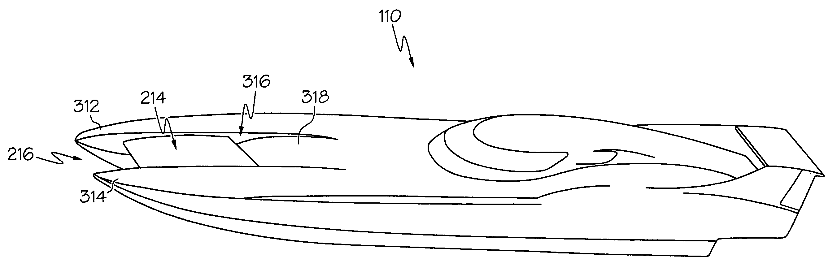
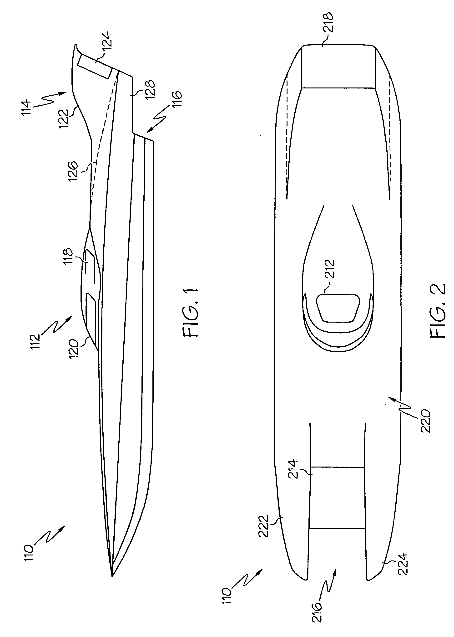
[0042]FIG. 1 depicts a side view of the catamaran boat first embodiment 110 according to the present invention, shown with a closed cockpit canopy 112 as is commonly utilized for competitive racing. A rear wing assembly 114 extends rearwardly beyond a transom 116. In the embodiment depicted an intake vent 118 is disposed on the side of the cockpit canopy 112 rearward of a cockpit windscreen 120. The intake vent 118 enables the catamaran 110 to provide an air supply to both its engines and any other mechanism that may utilize air pressure for operation. A pair of rising support members 122 of the rear wing assembly 114 is shown as including (optional) adjustable aerodynamic extensions 124 that are able to rotate about an inclined axis located p...


PUM


Abstract

A system for improving the performance of a powered boat that includes both methods and apparatuses that provide a powered boat means to stabilize, control, and optimize the powered boat's performance when the powered boat is in powered motion. The system provides capabilities of enhancing the powered boat's performance by responding to both aerodynamic and hydrodynamic effects upon the powered boat when the powered boat is in motion. Some embodiments of the system are capable of altering its means of response to aerodynamic effects while the powered boat is in powered motion, other embodiments are capable of altering the powered boat's response to hydrodynamic effects while the powered boat is in powered motion, and still other embodiments are capable of altering the powered boat's response to both aerodynamic and hydrodynamic effects while the powered boat is in powered motion. Certain embodiments of the system are capable of utilizing aerodynamic elements that operate on the air stream flowing within a tunnel formed within a multihull of a powered boat, while other embodiments are capable of mitigating the effects of water impacts upon the roof of a tunnel formed within a multihull powered boat. Still other embodiments are capable of responding to aerodynamic effects by interacting with portions of the air stream that passes above the boat while mitigating the potential for negative effects due to cross-winds impacting the structure which rises above a deck of the powered boat.

Description

CROSS-REFERENCE TO RELATED APPLICATIONS [0001] This non-provisional patent application claims the benefit of priority from U.S. provisional patent application Ser. No. 60 / 568982, inventors Scism, et al, filed on May 13, 2004.STATEMENT REGARDING FEDERALLY SPONSORED RESEARCH OR DEVELOPMENT [0002] Not applicable. BACKGROUND OF THE INVENTION [0003] 1. Field of the Invention [0004] The present invention relates generally to systems for controlling and improving the performance of power water craft by integrating the utilization of aerodynamic effects with the utilization of hydrodynamic effects, and more particularly by enabling these utilizations of aerodynamic and hydrodynamic effects to be alterable, and where said alterable utilizations are capable of functioning while the watercraft is in operation. [0005] 2. Related Art [0006] Efforts to improve the technologies utilized for marine transportation probably date back to the very advent of marine transportation. Among the more common ...

Claims


Application Information

Patent Timeline
Patent Type & Authority Applications(United States)
IPC IPC(8): B63B1/16B63B1/32
CPCB63B1/16Y02T70/12B63B1/322Y02T70/10
Inventor SCISM, RANDY MARKSCISM, GEORGE EDWARD
Owner SCISM RANDY MARK
Why Eureka
Try Eureka