Pressure relieving coupler manifold with internal velocity fuse

Active Publication Date: 2005-11-10
PARKER INTANGIBLES LLC
View PDF12 Cites 23 Cited by
  • Summary
  • Abstract
  • Description
  • Claims
  • Application Information

AI Technical Summary

Benefits of technology

[0011] More particularly, the decompression valve assembly is normally open thereby allowing thermal pressure build-up in an auxiliary circuit to be dissipated via a bleed path. During operation, the bleed path is sealed by a check valve, whereby high pressure flow can be fully directed to the work tool powered by the auxiliary circuit, for high system efficiency. In addition, a velocity fuse feature limits the rate of flow to the bleed path, thereby to allow for controlled release of pressure from the auxiliary circuit, as is desirable to protect against a rapidly falling load.
[0012] Consequently, principles of the present invention can be applied to avoid one or more drawbacks associated with prior art quick coupling systems, including the elimination of the need for connect under pressure couplers that contain specialized internal valving, thereby allowing the use of standard couplers; the elimination or reduction of thermal pressure buildup in the auxiliary circuits; the elimination of the need for elastomeric seals previously required in some systems to throttle flow, and others.
[0013] Accordingly, the present invention provides a quick coupling system comprising a fluid circuit including a quick coupling, and a decompression valve assembly that, when actuated, allows internal hydraulic pressure in the fluid circuit to be released to a bleed path, wherein the decompression valve assembly is normally open thereby allowing thermal pressure build-up in the fluid circuit to be dissipated to the bleed path, the decompression valve assembly is closed by high pressure flow in the fluid circuit, and the decompression valve assembly includes a velocity fuse that limits the rate of flow to the bleed path, thereby to provide for controlled decompression of the auxiliary circuit.

Problems solved by technology

Such internal hydraulic pressure can be residual hydraulic pressure from operating the attachment, or may be due to thermal hydraulic pressure buildup in the hydraulic circuit.
Regardless, hydraulic pressure in the circuit can make forming the connection more difficult, especially with standard quick-disconnect couplers.
For the user, it becomes increasingly difficult to make a connection as internal pressure, and thus hydraulic force, on the valves of the two couplers to be connected increases.
In the hydraulic coupling industry, difficulty in making a connection due to hydraulic pressure is known as the “connect under pressure” problem.
Such couplers are more complex and cost more than a standard coupler (i.e., couplers without internal valving) due to the internal valving.
Further, many prior art coupler designs utilize elastomeric seals that are required to throttle flow during connect under pressure.
It is well known that throttling flow over elastomeric seals increases the potential for seal damage and often results in such.
Many prior art coupler designs also involve the need for operator training as the operation of the couplers is not intuitive.

Method used


Image

  • Pressure relieving coupler manifold with internal velocity fuse
  • Pressure relieving coupler manifold with internal velocity fuse
  • Pressure relieving coupler manifold with internal velocity fuse

Examples


Embodiment Construction

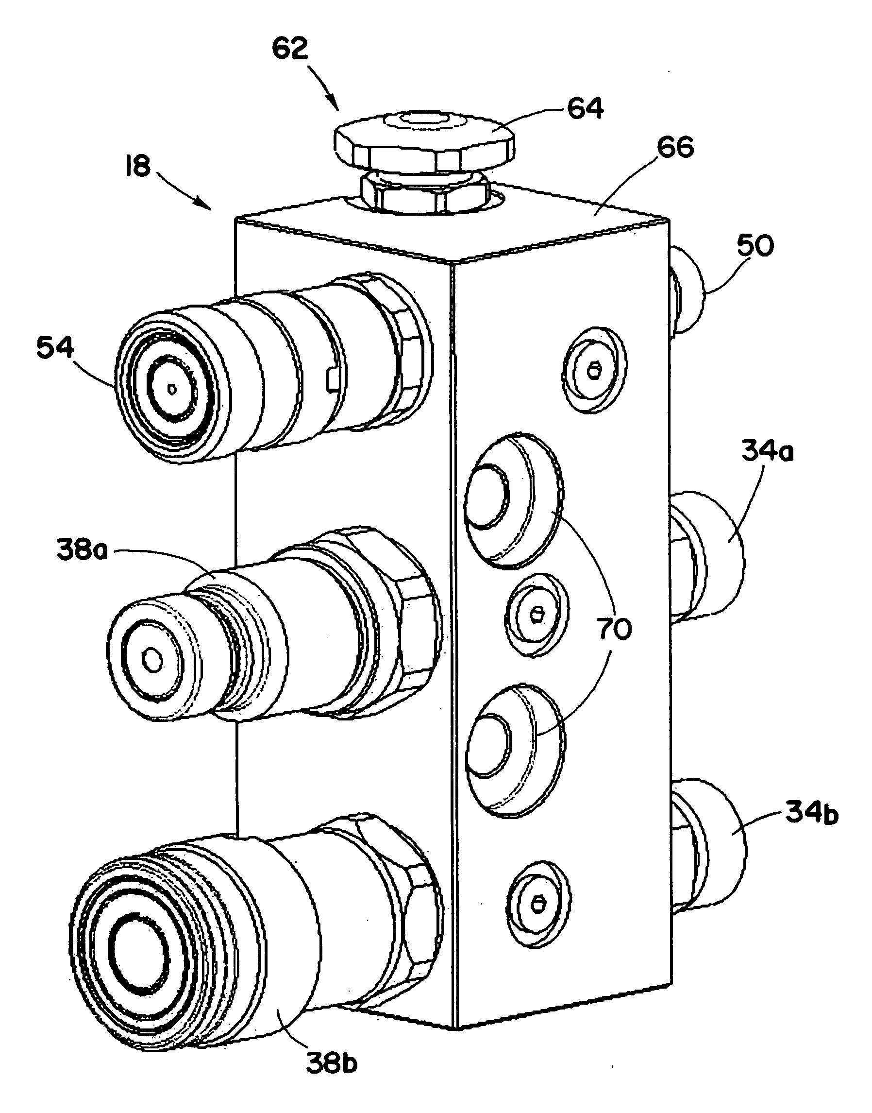
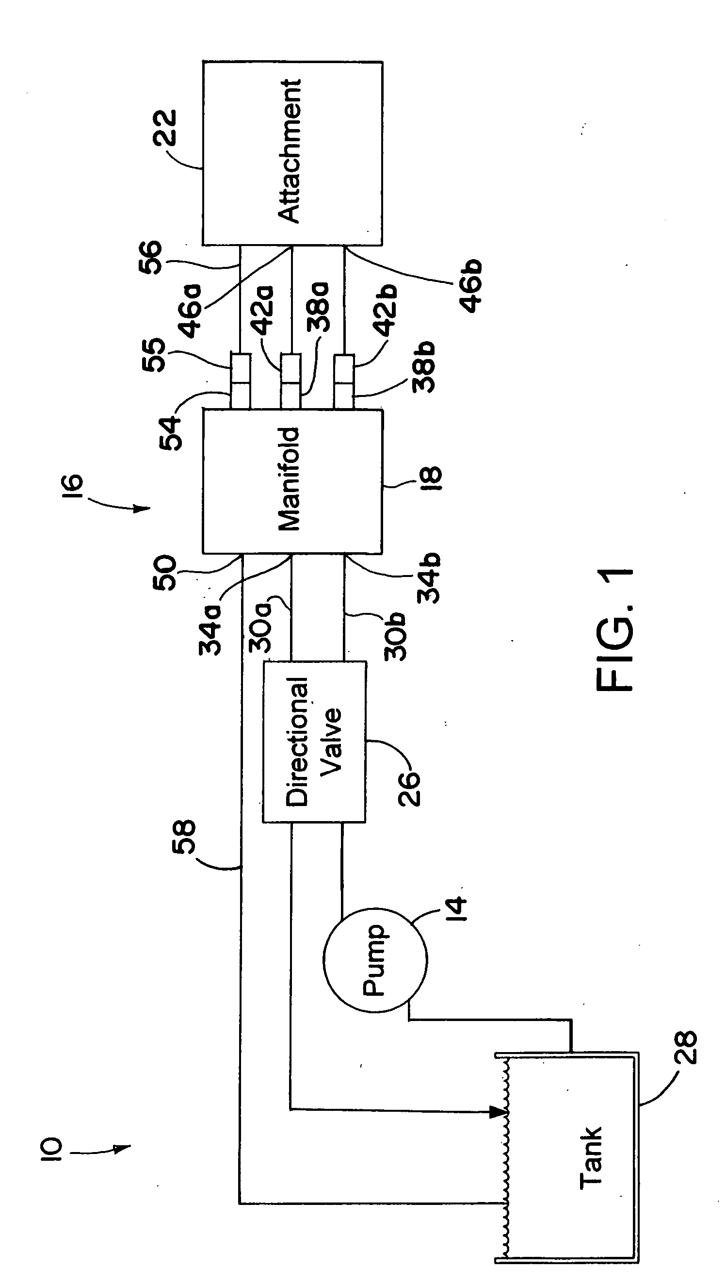
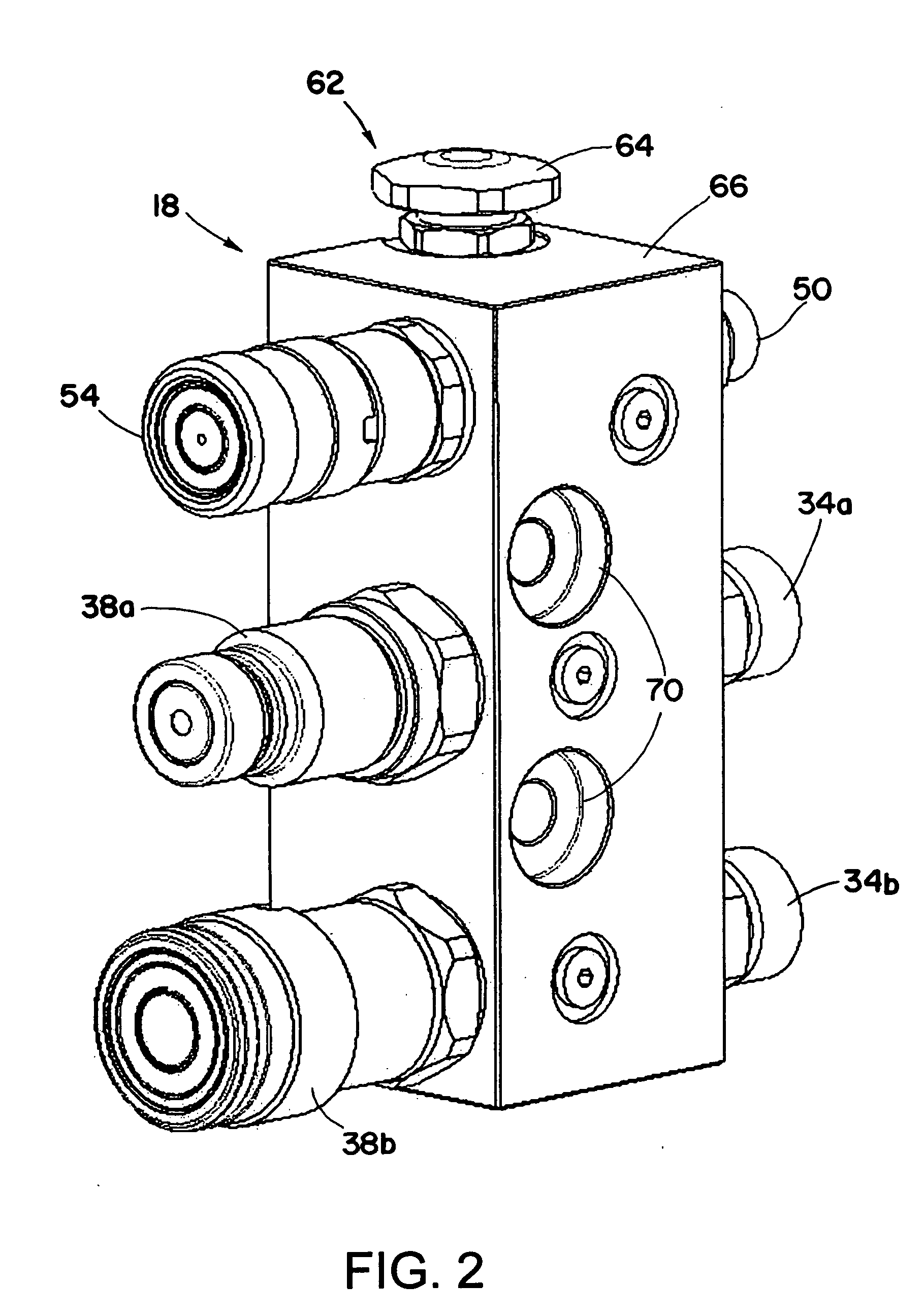
[0031] Referring now to the drawings in detail, and initially to FIG. 1, an exemplary hydraulic circuit 10 generally comprises a pump 14, a coupler system 16, and an attachment 22. In the illustrated embodiment, which is particularly suited for use in a mini-excavator, skid-steer loader, or similar type of machinery, there is a directional control valve 26 that directs pressurized fluid from the pump 14, which draws fluid from a tank 28, to either hydraulic line 30a or 30b depending on the desired direction of operation of the attachment 22. Hydraulic lines 30a and 30b are connected to the coupler system 16 which includes a manifold 18. More particularly, the lines 30a and 30b are connected to manifold ports 34a and 34b, respectively. Manifold ports 34a and 34b are connected internally via the manifold 18 to manifold coupler halves 38a and 38b, respectively.

[0032] In the illustrated embodiment, coupler half 38a is a male coupler half and coupler half 38b is a female coupler half, t...


PUM


Abstract

A decompression valve assembly is normally open thereby allowing thermal pressure build-up in an auxiliary circuit to be dissipated via a bleed path. During operation, the bleed path is sealed by a check valve, whereby high pressure flow can be fully directed to the work tool powered by the auxiliary circuit, for high system efficiency. In addition, a velocity fuse feature limits the rate of flow to the bleed path, thereby to allow for controlled release of pressure from the auxiliary circuit, as is desirable to protect against a rapidly falling load.

Description

RELATED APPLICATION [0001] This application claims the benefit of U.S. Provisional Application No. 60 / 568,200 filed May 5, 2004, which is hereby incorporated herein by reference.FIELD OF THE INVENTION [0002] The present invention relates generally to fluidic systems and more particularly to a quick-disconnect coupler manifold including a decompression valve assembly for relieving pressure from pressure lines for facilitating coupling of, for example, auxiliary hydraulic system components. BACKGROUND OF THE INVENTION [0003] A trend in the construction industry has been to utilize smaller, more versatile machinery on the job-site. For example, mini-excavators and skid-steer loaders are often used to perform a variety of tasks. In many cases, a skid-steer loader or mini-excavator is equipped with an attachment for performing a particular task. Such attachments are typically powered by an auxiliary hydraulic circuit on the skid-steer loader or mini-excavator. Numerous attachments exist ...

Claims


Application Information

Patent Timeline
IPC IPC(8): F16K27/00F16L37/40F16L41/03
CPCF16K27/003F16L37/40E02F9/2275F16L37/56E02F3/325F16L41/03Y10T137/7782Y10T137/7835Y10T137/87845Y10T137/87949
Inventor HISER, NICHOLAS R.
Owner PARKER INTANGIBLES LLC
Why Eureka
Try Eureka