Illumination device with a phosphor

Active Publication Date: 2012-03-08
SIGNIFY HOLDING B V
View PDF2 Cites 27 Cited by
  • Summary
  • Abstract
  • Description
  • Claims
  • Application Information

AI Technical Summary

Benefits of technology

[0004]It is an object of the invention to provide a possibility to gain a high light extraction efficiency from a single surface of a luminescent material in conjunction with a high system efficiency.
[0018]It is an essential idea of the invention to use a transparent phosphor in combination with a transparent material in such a geometrical configuration comprising an increased effective escape surface area in the phosphor with respect to the area pump light enters the phosphor. In this way, a high emission is obtained from a single surface with a large effective area when the surface light enters the phosphor. In this way it is possible that more than three times as much light is emitted from the surface opposite to the pumped surface.

Problems solved by technology

Therefore, it is difficult to avoid light being emitted by the phosphor (phosphor light) propagating in the direction of the pump source, such as a light emitting diode, LED for short, or a laser.
In case of a LED phosphor light propagating in the direction of the LED is partially absorbed reducing the efficiency of the system.

Method used


Image

  • Illumination device with a phosphor
  • Illumination device with a phosphor
  • Illumination device with a phosphor

Examples


Embodiment Construction

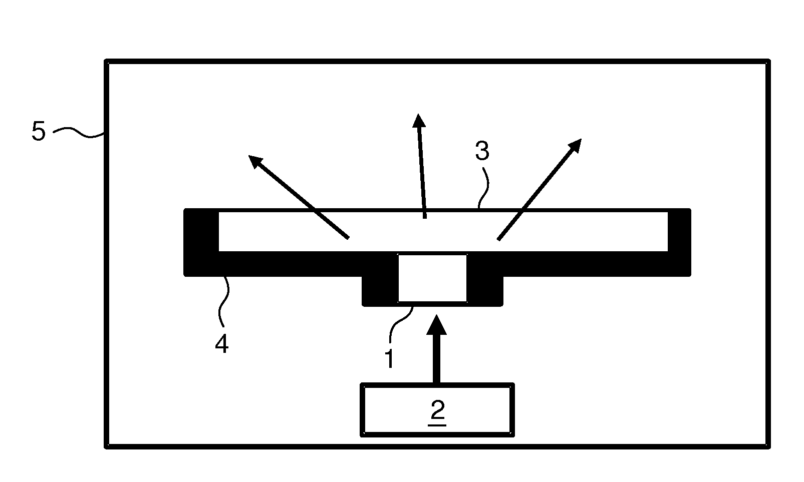
[0038]FIG. 1 shows a basic configuration of an illumination device 5 according to a first preferred embodiment of the invention. The effective area of the exit surface or the exit surface of the waveguide 3 is increased with respect to the pump light entrance surface or the exit surface of the phosphor 1. The waveguide 3 corresponds to a transparent waveguide or a transparent phosphor, respectively. The illumination device 5 with a phosphor 1 comprises an exit surface adapted for emitting optical radiation, in other words emitting luminescent optical radiation or luminescent light, and a side surface surrounding the phosphor 1. A light source 2 is provided which is adapted for emitting optical radiation directed to the phosphor 1. The phosphor 1 is capable of converting at least part of the wavelength of radiation emitted from the light source to a wavelength different from the wavelength of radiation emitted. The light source corresponds to a solid state light source, such as a lig...


PUM


Abstract

The invention relates to an illumination device and a method adapted for illuminating applications. The illumination device (5) with a phosphor (1) comprising at least one light emitting surface which is adapted for emitting phosphor light in a predefined solid angle, a light source (2) being adapted for emitting optical radiation directed to the phosphor (1), a waveguide (3), and a reflector (4), wherein the phosphor (1) is optically coupled to the waveguide (3), the exit surface of the illumination device (5) from which light is emitted is larger than any single light emitting surface of the phosphor (1), and the reflector (4) is adapted for reflecting at least a part of the optical radiation emitted from the illumination device (5) by a surface different from the exit surface of the illumination device (5). In this way, a high light extraction efficiency from a single surface of a luminescent material and at the same time a high quantum efficiency of the illumination device is achieved.

Description

FIELD OF THE INVENTION[0001]The invention relates to the field of illumination devices comprising a phosphor and to the field of methods, adapted for illuminating applications.BACKGROUND OF THE INVENTION[0002]Document WO 2007 / 044472 A2 describes an efficient or higher luminance light emitting diode assembly which may be formed from a high power light emitting diode chip having a first surface and a second surface, the first surface being mounted to a substrate, wherein the second surface is in intimate thermal contact with a light transmissive heat sink having a thermal conductivity larger than 30 Watts per meter-Kelvin. The LED chip is otherwise in electrical contact with at least a first electrical connection and a second electrical connection for powering the LED chip. Providing light transmissive heat sink doubles the heat conduction from the LED dies thereby avoids excess heating of the phosphor increasing life and / or efficiency and / or luminance and / or a balance of the three.[0...

Claims


Application Information

Patent Timeline
IPC IPC(8): H01P5/00F21V29/00F21V5/04F21V9/14F21V9/16F21V9/40
CPCG02B6/0056H01L33/60H01L33/58H01L33/507F21V13/14
Inventor HIKMET, RIFAT ATA MUSTAFA
Owner SIGNIFY HOLDING B V
Why Eureka
Try Eureka