Planar light source device

Active Publication Date: 2011-08-18
ZEON CORP
View PDF8 Cites 8 Cited by
  • Summary
  • Abstract
  • Description
  • Claims
  • Application Information

AI Technical Summary

Benefits of technology

[0010]The planar light source device of the present invention has high light extraction efficiency, and a small change in color tone at different viewing angles. Therefore, the planar light source device of the present invention is useful as, for example, a light source of a lighting device or a backlight unit for a display device such as a liquid crystal display device.

Problems solved by technology

However, the efficiency of currently known white organic EL devices is not high enough for lighting applications described above.
Therefore, when the above structures are used in such organic EL devices, there occurs a problem in that the color tone when the light emitting surface is viewed from a front direction is significantly different from the color tone when the light emitting surface is viewed at an oblique angle with respect to the front direction.

Method used


Image

  • Planar light source device
  • Planar light source device
  • Planar light source device

Examples


example 1

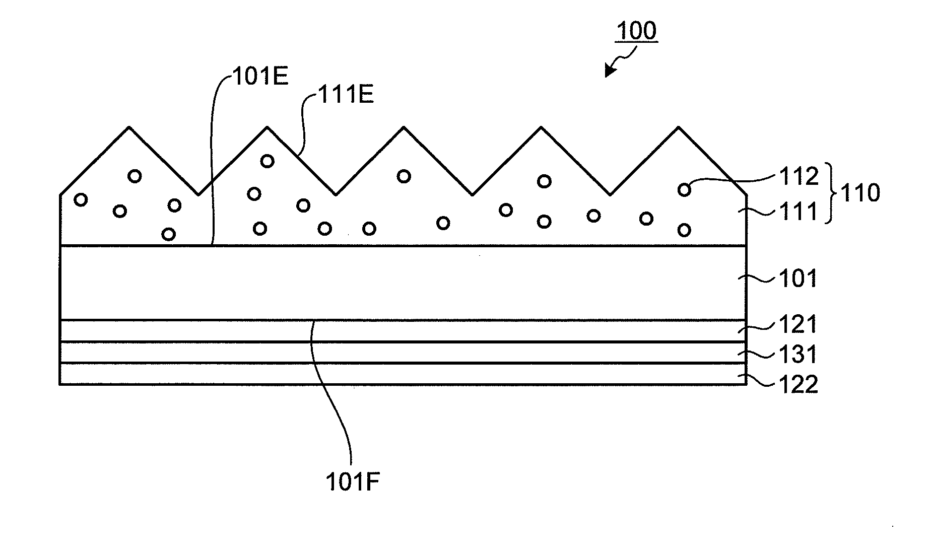
[0099]Spherical SiO2 particles (n=1.43) having a diameter of 2 μm were added to a UV (ultraviolet ray) curable urethane acrylic resin (refractive index after curing: n=1.53) in an amount of 3 wt % based on the total amount of the composition. The mixture was stirred to disperse the particles, and a resin composition was thereby obtained.

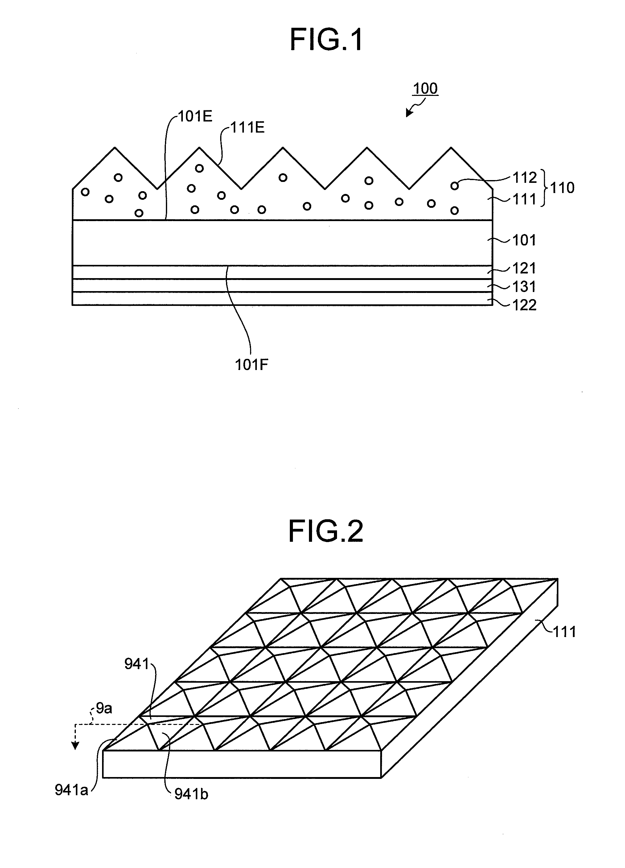
[0100]The obtained resin composition was applied to a glass substrate to a thickness of 100 μm. Then a metal mold having a predetermined shape was pressed against the resin composition, and the resin composition was irradiated through the glass substrate with UV rays at an accumulated light quantity of 1,000 mJ / cm2 to form a concavo-convex structure layer on the substrate. In this concavo-convex structure, quadrangular pyramids each having a square bottom shape of 50 μm side and a apex angle of 90° were arranged without gaps therebetween. The angle between the light emitting surface and the inclined surfaces of the quadrangular pyramids was 45°. The ...

example 2-1

(2-1-1: Concavo-Convex Structure Layer)

[0121]Spherical SiO2 particles (n=1.43) having a diameter of 2 μm were added to a UV (ultraviolet ray) curable urethane acrylic resin (refractive index after curing: n=1.53) in an amount of 3 wt % based on the total amount of the composition. The mixture was stirred to disperse the particles, and a resin composition was thereby obtained.

[0122]The obtained resin composition was applied to a transparent film (product name “ZEONOR Film,” product of ZEON Corporation, thickness: 180 μm) to a thickness of 100 μm. Then a metal mold having a predetermined shape was pressed against the resin composition, and the resin composition was irradiated through the transparent film with UV rays at an accumulated light quantity of 5,000 mJ / cm2 to form a concavo-convex structure layer on the transparent film, whereby a layered stack having a layer structure of (the transparent film)-(the concavo-convex structure layer) was obtained. In the concavo-convex structure...

example 2-2

(2-2-1: Concavo-Convex Structure Layer)

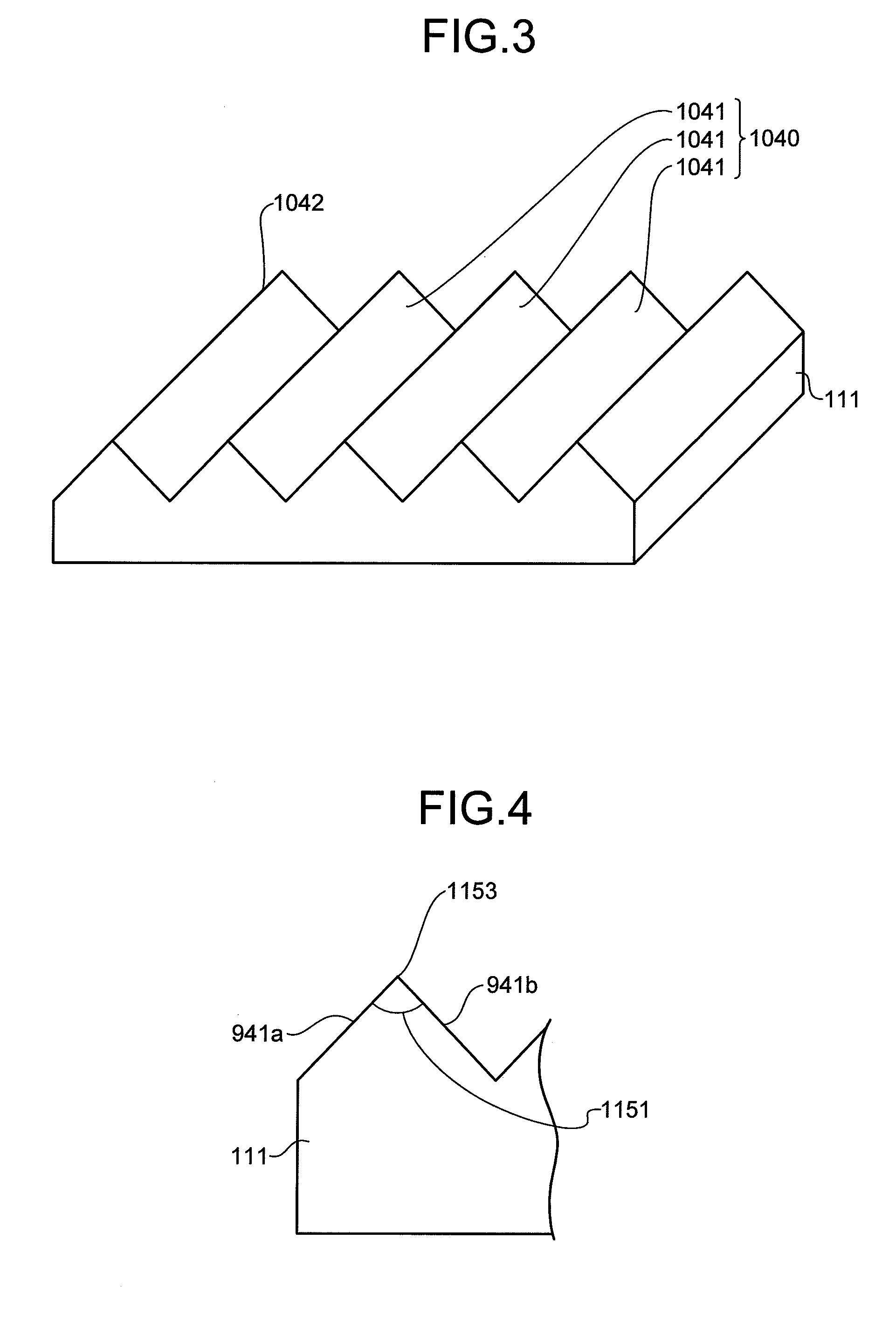
[0135]A layered stack having a layer structure of (the transparent film)-(the concavo-convex structure layer) was obtained by the same procedure as in (2-1-1) of Example (2-1) except that the shape of the metal mold was changed. In the concavo-convex structure of this concavo-convex structure layer, quadrangular pyramid-shaped recesses each having a square bottom shape of 50 μm side and a apex angle of 90° were arranged without gaps therebetween. The angle between the light emitting surface and the inclined surfaces of the quadrangular pyramids was 45°.

(2-2-2: Planar Light Source Device)

[0136]A planar light source device was produced and evaluated by the same procedure as in (2-1-2) and (2-1-3) in Example (2-1) except that a stack obtained in (2-2-1) was used instead of the stack obtained in (2-1-1). The results are shown in FIG. 15.


PUM


Abstract

A planar light source device is provided which has high light extraction efficiency and in which a change in color tone at different viewing angles is small. The planar light source device includes, on a light emitting surface, a concavo-convex structure layer made of a resin composition. In this planar light source device, the concavo-convex structure layer has a cone, pyramid, or prism shape, and the resin composition contains a transparent resin and particles. In particular, in the planar light source device, variations in any of x- and y-chromaticity coordinates in any directions in a hemisphere on the light emitting surface are within ±0.1, the diameter of the particle is 10 μm or less, and the amount of the particles is 1 to 40 wt % based on the total amount of the resin composition. In addition, the difference in refractive index between the particles and the transparent resin is 0.05 to 0.5.

Description

TECHNICAL FIELD[0001]The present invention relates to a planar light source device.BACKGROUND ART[0002]The luminescent bodies of organic electroluminescent devices (hereinafter may be referred to as “organic EL devices”) can be formed in a planar shape, and the color of light generated therefrom can be white or a color close to white. Therefore, such organic electroluminescent devices can be used as light sources of lighting devices or in applications of backlight units for display devices.[0003]White organic EL devices are produced as organic EL devices used in lighting applications. Many of such white devices are called the stacked or tandem type in which luminescent layers that generate complementary colors are stacked. The stacks of such luminescent layers are mainly stacks of yellow-blue layers or green-blue-red layers.[0004]However, the efficiency of currently known white organic EL devices is not high enough for lighting applications described above. Therefore, in order to us...

Claims


Application Information

Patent Timeline
IPC IPC(8): H01J1/62
CPCB82Y20/00B82Y30/00G02B5/02H05B33/14H01L51/5275H01L2251/5369H01L51/5268H10K50/854H10K50/858H10K2102/331
Inventor YAMADA, YASUMIINOUE, HIROYASU
Owner ZEON CORP
Why Eureka
Try Eureka