Surface light source device, lighting device, and backlight device

Inactive Publication Date: 2012-04-05
ZEON CORP
View PDF8 Cites 19 Cited by
  • Summary
  • Abstract
  • Description
  • Claims
  • Application Information

AI Technical Summary

Benefits of technology

[0038]The surface light source device of the first invention has high light extraction efficiency and can reduce the change in color tone at different viewing angles, and the light-emitting surface of the device has high mechanical strength. Therefore, the surface light source device is useful as the light source of a lighting device and the backlight of a display device such as a liquid crystal display device.
[0039]The lighting device and backlight device of the first invention include the surface light source device of the first invention. Therefore, the lighting device and the backlight device can have high light extraction efficiency and high mechanical strength and can reduce the change in color tone at different viewing angles.
[0040]The surface light source device of the second invention has advantages in that it can be produced with high productivity because problems such as warpage of the product do not occur, can contribute to a reduction in the size of the device, and can suppress the change in color tone at different viewing angles. Since the surface light source device has such advantages, it is useful as the light source of a lighting device and the backlight device for a liquid crystal display device.

Problems solved by technology

However, currently known organic EL elements are unsatisfactory in terms of efficacy for the aforementioned lighting applications.

Method used


Image

  • Surface light source device, lighting device, and backlight device
  • Surface light source device, lighting device, and backlight device
  • Surface light source device, lighting device, and backlight device

Examples


embodiment 1-1

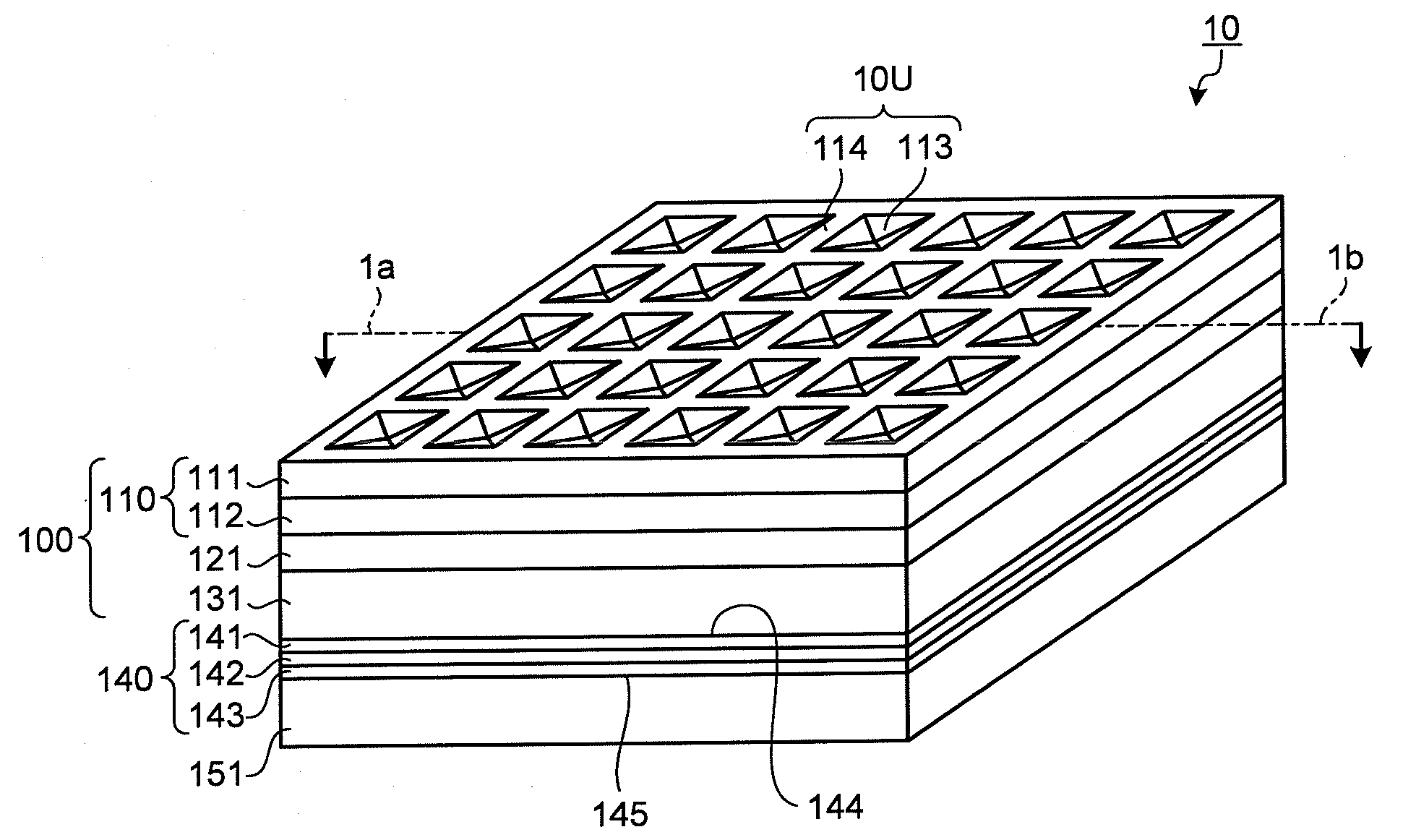
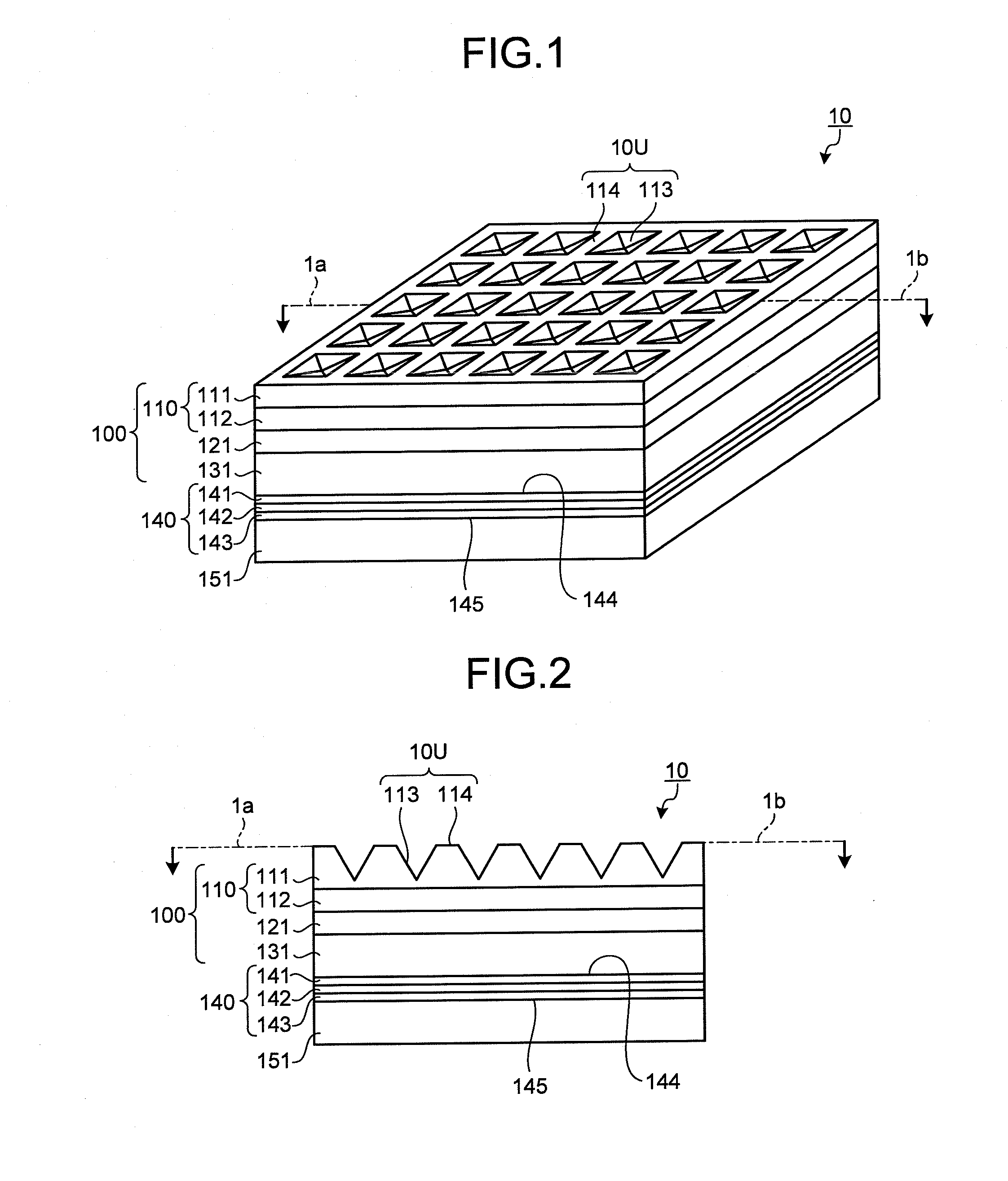
[0073]The first invention will be described in more detail with reference to the drawings.

[0074]A surface light source device of the first invention includes: an organic EL element including a luminescent layer; and a light-emitting surface structure layer that is disposed in contact with at least one surface of the organic EL element and defines a concave-convex structure on the surface on the device light-emitting surface side.

[0075]The device light-emitting surface is the light-emitting surface of the surface light source device, i.e., the light-emitting surface from which the light from the surface light source device is emitted to the outside of the device. The device light-emitting surface is a surface parallel to the luminescent layer of the organic EL element and is parallel to the principal surface of the surface light source device. However, in a microscopic sense, the surfaces of concave portions described later may form a non-parallel angle with respect to the luminescen...

embodiment 1-2

[0147]In the surface light source device of the first invention, the shape of the concave portions constituting the device light-emitting surface is not limited to the pyramid shape exemplified in Embodiment 1-1 described above. For example, the concave portions may have a shape that is part of a sphere as in Embodiment 1-2 which will be described below.

[0148]Embodiment 1-2 is a second embodiment according to the first invention. FIG. 7 is a top view schematically showing a surface light source device according to Embodiment 1-2, and FIG. 8 is a cross-sectional view showing a cross-section obtained by cutting the surface light source device shown in FIG. 7 along a plane that passes through line 2a in FIG. 7 and is perpendicular to the device light-emitting surface. As shown in FIGS. 7 and 8, the surface light source device 20 according to Embodiment 1-2 has the same configuration as that of Embodiment 1-1 except that the shape of the device light-emitting surface, i.e. the surface s...

embodiment 1-3

[0151]In the surface light source device of the first invention, the shape of the concave portions constituting the device light-emitting surface may also be a groove shape as in Embodiment 1-3 which will be described below.

[0152]Embodiment 1-3 is a third embodiment according to the first invention. FIG. 9 is a perspective view schematically showing the surface light source device according to Embodiment 1-3. As shown in FIG. 9, the surface light source device 30 according to Embodiment 1-3 has the same configuration as that of Embodiment 1-1 except that the shape of the device light-emitting surface, i.e. the surface shape of a concave-convex structure layer 311 in a multi-layered body 310 constituting a light-emitting surface structure layer 300, is different from that in the first embodiment.

[0153]Each of a plurality of concave portions 313 formed on the surface of the concave-convex structure layer 311 has a linear groove shape and includes two flat oblique surfaces. Therefore, ...


PUM


Abstract

A surface light source device is provided that has high light extraction efficiency and high mechanical strength and can suppress a change in color tone at different viewing angles. To that end, the surface light source device includes: an organic EL element including a luminescent layer; and a light-emitting surface structure layer that is disposed in contact with one of the surfaces of the organic EL element and defines a concave-convex structure on the surface on the device light-emitting surface side. The concave-convex structure includes a plurality of concave portions having oblique surfaces and flat portions disposed around the concave portions. The surface light source device further includes a diffusing member on which the light emitted from the luminescent layer is incident, the diffusing member allowing the incident light to pass therethrough or reflecting the incident light in a diffused manner.

Description

TECHNICAL FIELD[0001]The present invention relates to a surface light source device, a lighting device provided with the surface light source device, and a backlight device provided with the surface light source device.BACKGROUND ART[0002]The luminescent bodies of organic electroluminescent elements (hereinafter may be referred to as “organic EL elements”) can be formed in a planar shape, and the color of light emitted therefrom can be white or a color close to white. Therefore, it is contemplated that such organic EL elements are used as light sources of lighting devices for illuminating areas in living environments etc. or in applications for backlights of display devices.[0003]As an example of the organic EL elements used in lighting applications, white organic EL elements are being manufactured. Many of such white elements are of the stacked or tandem type in which luminescent layers that emit light with complimentary colors are stacked. The stacks of such luminescent layers are...

Claims


Application Information

Patent Timeline
IPC IPC(8): H01L51/52
CPCG02B5/045G02B6/0036H01L51/5275G02F2001/133607G02F1/133603G02F1/133607H10K59/877H10K59/878H10K59/879H10K59/871H05B33/14H10K50/854H10K50/84H10K50/856H10K50/858
Inventor INOUE, HIROYASUHORI, TOSHIHIKO
Owner ZEON CORP
Why Eureka
Try Eureka