Pallet conveyor with chain drive recirculating in a horizontal plane

a conveyor and horizontal plane technology, applied in the field of conveyors, can solve the problems of large disadvantages, waste of space, and high manufacturing cost, and achieve the effect of simple and reliable arrangemen

Active Publication Date: 2005-11-10
ROBERTS SINTO A MICHIGAN
View PDF34 Cites 30 Cited by
  • Summary
  • Abstract
  • Description
  • Claims
  • Application Information

AI Technical Summary

Benefits of technology

[0013] It is another object to provide a simplified and reliable arrangement for selectively engaging and

Problems solved by technology

This creates wasted space between advance and return runs of the conveyor which wasted space is a significant disadvantage when installed in the confines of a typical manufacturing facility.
In an accum

Method used


Image

  • Pallet conveyor with chain drive recirculating in a horizontal plane
  • Pallet conveyor with chain drive recirculating in a horizontal plane
  • Pallet conveyor with chain drive recirculating in a horizontal plane

Examples


Embodiment Construction

[0042] In the following detailed description, certain specific terminology will be employed for the sake of clarity and a particular embodiment described in accordance with the requirements of 35 USC 112, but it is to be understood that the same is not intended to be limiting and should not be so construed inasmuch as the invention is capable of taking many forms and variations within the scope of the appended claims.

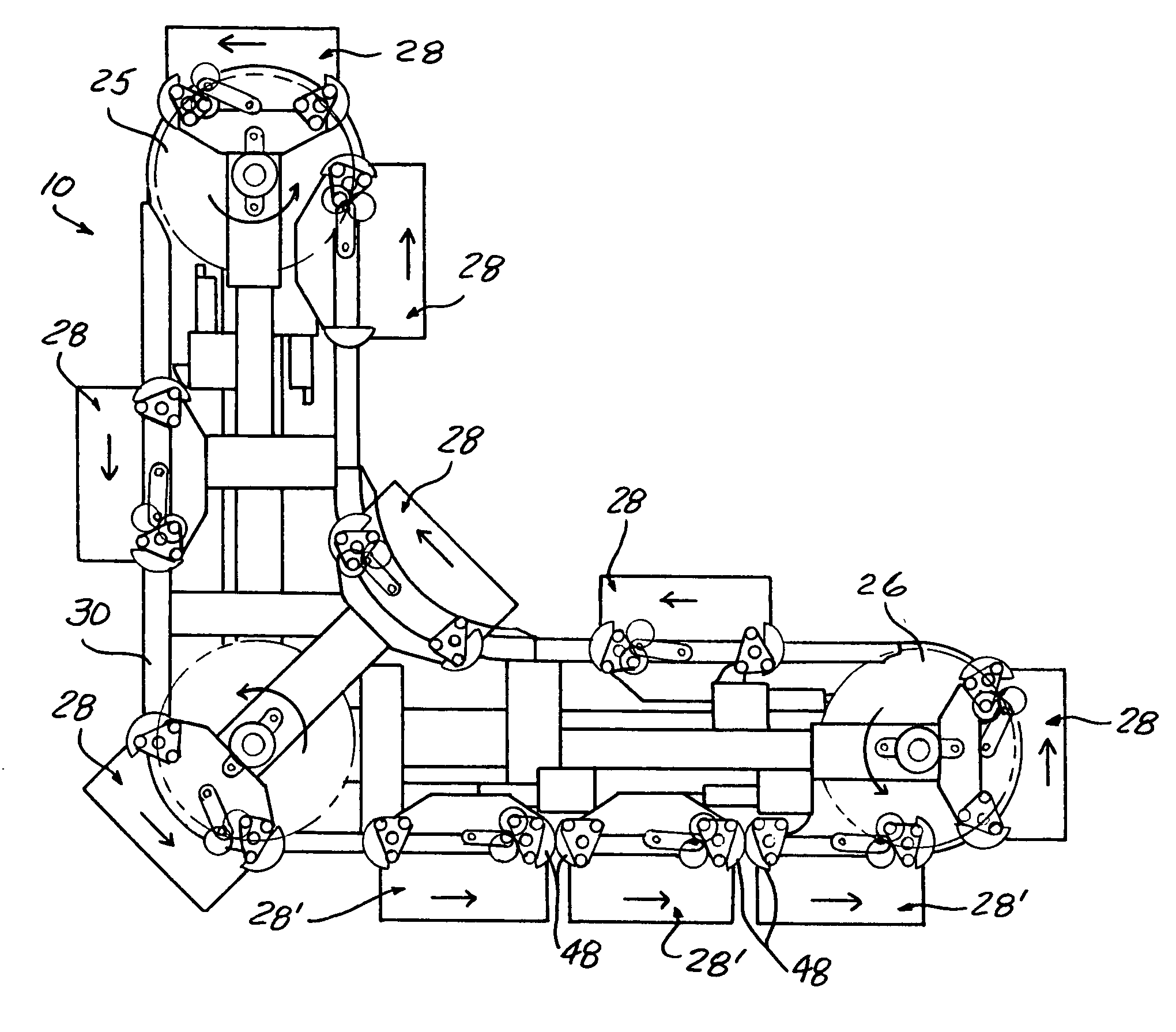
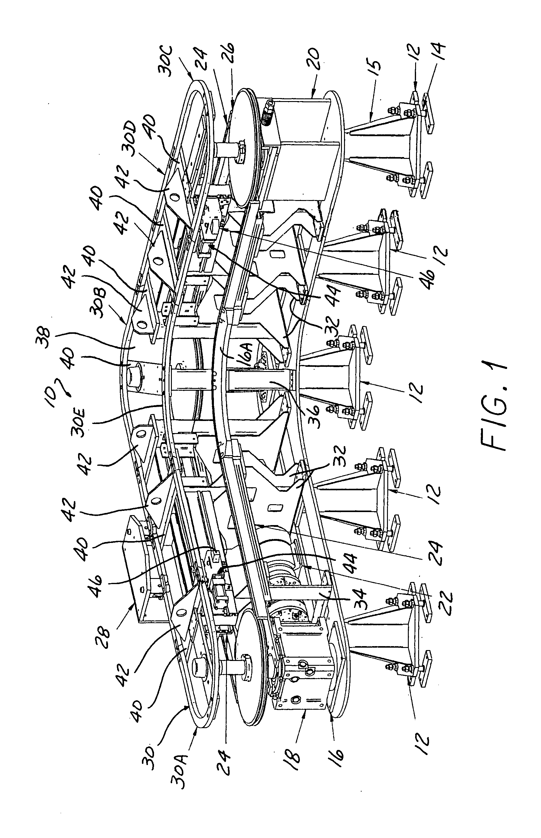
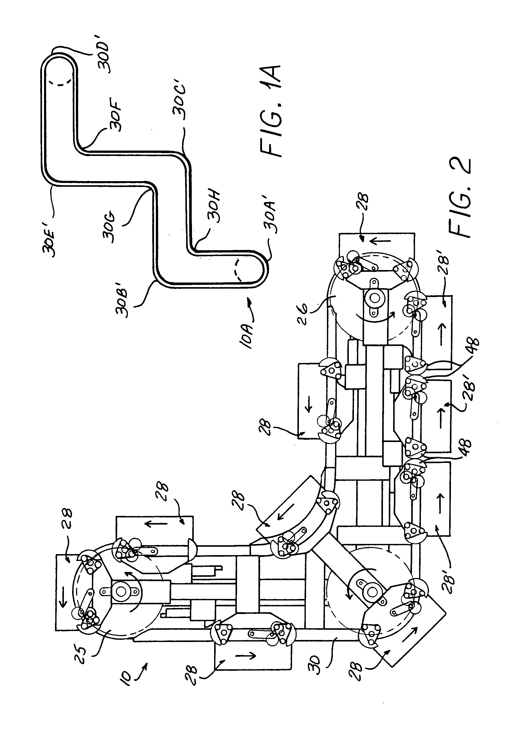
[0043] Referring to the drawings and particularly FIGS. 1-3, a conveyor 10 according to the invention is supported above the floor on a series of stanchion assemblies 12, including a series of leveling screws 14 and a gusset-tube weldment 15.

[0044] A support-guide plate 16 is attached to the stanchions assemblies 12, and holds a sprocket drive unit 18 at one end and an idler-tensioner sprocket unit 20 at the other end of the conveyor 10. A drive motor 22 is included in the sprocket drive unit 18, a chain drive sprocket 25 thereby rotated to advance a multi strand link...


PUM


Abstract

A conveyor using a drive chain to drive pallets along a closed loop path on a track lying in a horizontal plane through inside and outside turns so that the conveyor may transport parts along non aligned stations. An advance and a return run extend parallel to each other and are closely spaced to minimize the floor space required. The drive chain is engaged by two spaced apart sprockets engaging a respective side of the drive chain, the sprockets mounted to the pallet on a pivoted bar spring biased to urge the sprocket teeth into engagement with the chain. The sprocket bar is pivotally mounted to one end of the swing bar which has an opposite end connected to the pallet to allow the chain and pallet to move together along the track and negotiate inside and outside turns. The chain is guided in a chain guide channel through inside turns, and on sprockets around the outside turns. A pair of friction brake rollers are included, each attached to one of the sprockets and are normally in firm contact with each other to brake the sprockets and carry the pallet along with the chain, which friction brake rollers slip when the pallet is arrested by a stop mechanism to be allowed to accumulate, the sprockets then able to rotate and the chain allowed to continue to circulate past the stopped pallet. The pallets extend alongside the chain and track to allow vertical mounting of parts on a side plate of the pallet or alternatively on a horizontal top plate. Alternatively, the swing bars can each be connected to the chain by one of a series of pins connected to the drive chain and pivotally received in the swing bar end in a synchronous nonaccumulating conveyor.

Description

CROSS REFERENCE TO RELATED APPLICATIONS [0001] This application claims the benefit of U.S. provisional Ser. No. 60 / 568,938, filed May 6, 2004.BACKGROUND OF THE INVENTION [0002] This invention concerns conveyors, and more particularly conveyors in which a series of pallets are driven around a closed loop track by a recirculating link chain, parts to be conveyed thereby being carried by the pallets. Such conveyors are commonly used in moving parts through a series of workstations where processes are performed on the parts. [0003] Conveyors are sometimes designed as “accumulator” or asynchronous conveyors, allowing pallets to form a queue at one or more stations by disengaging the drive connection of the pallets to the drive chain so that the drive chain can overrun the queued pallets. Conveyors are also designed to the “synchronous”, in which the pallets always remain in driving engagement with the drive chain and always move in synchronism with the chain. [0004] Many such conveyors a...

Claims


Application Information

Patent Timeline
IPC IPC(8): B23Q7/03B23Q7/14B65G15/00B65G17/02B65G17/18B65G17/22B65G17/42B65G17/48B65G21/20B65G21/22B65G23/06
CPCB65G17/22B23Q7/1447
Inventor STRANGE, DAVID M.
Owner ROBERTS SINTO A MICHIGAN
Why Eureka
Try Eureka