
3D modeling device and 3D modeling method for supplying material with high precision

a 3d modeling and material technology, applied in the direction of additive manufacturing processes, applications, manufacturing tools, etc., can solve the problems of deterioration of the quality of the completed 3d object, waste of modeling materials, and damage to the nozzl

Active Publication Date: 2005-11-10
ROLAND DG CORP
View PDF6 Cites 83 Cited by
  • Summary
  • Abstract
  • Description
  • Claims
  • Application Information

AI Technical Summary

Benefits of technology

The present invention provides a 3D modeling device and method that can make high-quality 3D objects. The device includes a subsidiary material supplying unit, a modeling material supplying unit, a processing machine, and a controller. The subsidiary material layer and the modeling material layer are repeatedly processed to achieve high precision. The modeling material can be a light-curing resin that is cured by irradiation of light. The device can also use a low melting point alloy or a light-curing resin in the form of dots. The technical effects of the invention are improved quality and precision of 3D objects.

Problems solved by technology

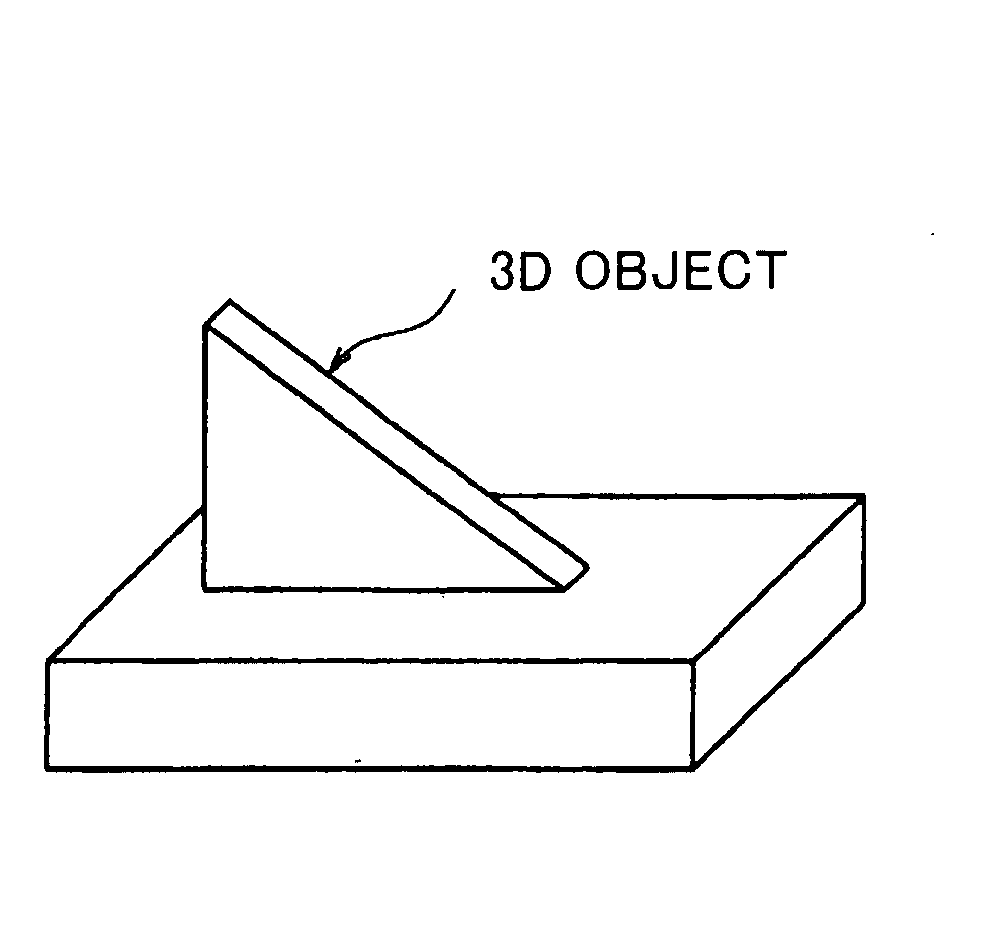
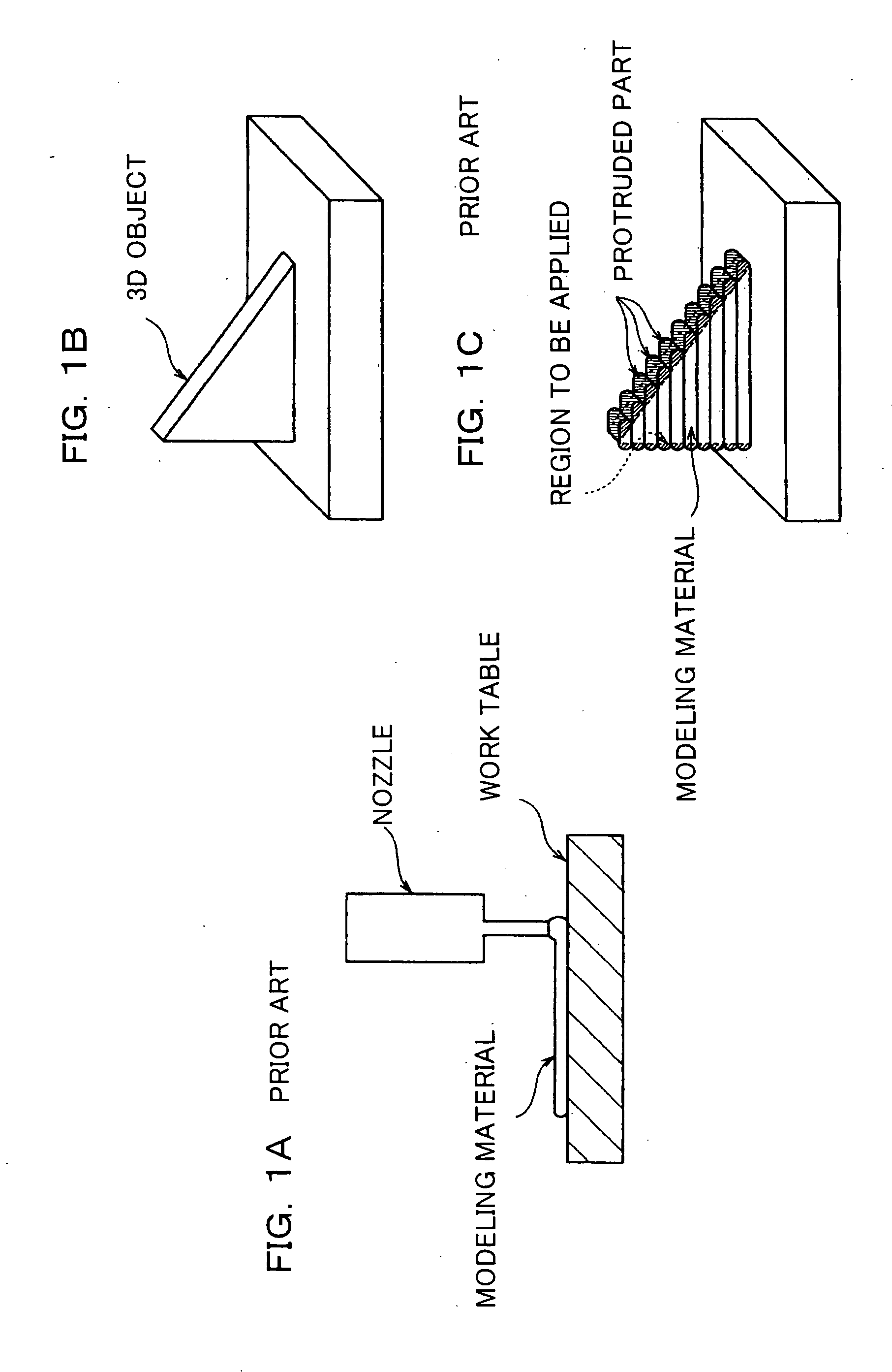
When a 3D object such as an almost triangle-shaped wall shown in FIG. 1B is made by a conventional linear application method in which a modeling material is applied from a nozzle linearly, for example, since the modeling material is applied from the nozzle linearly while the tip end of the nozzle is considerably close to a worktable (refer to a view shown in FIG. 1A), the nozzle could be damaged because it comes in touch with the worktable.
In addition, according to the conventional linear application method, ends of the linearly applied modeling material protrude from a predetermined region in which the modeling material is to be applied (a part shown by a hatching in FIG. 1C is the protruded part), so that the modeling material is wasted.
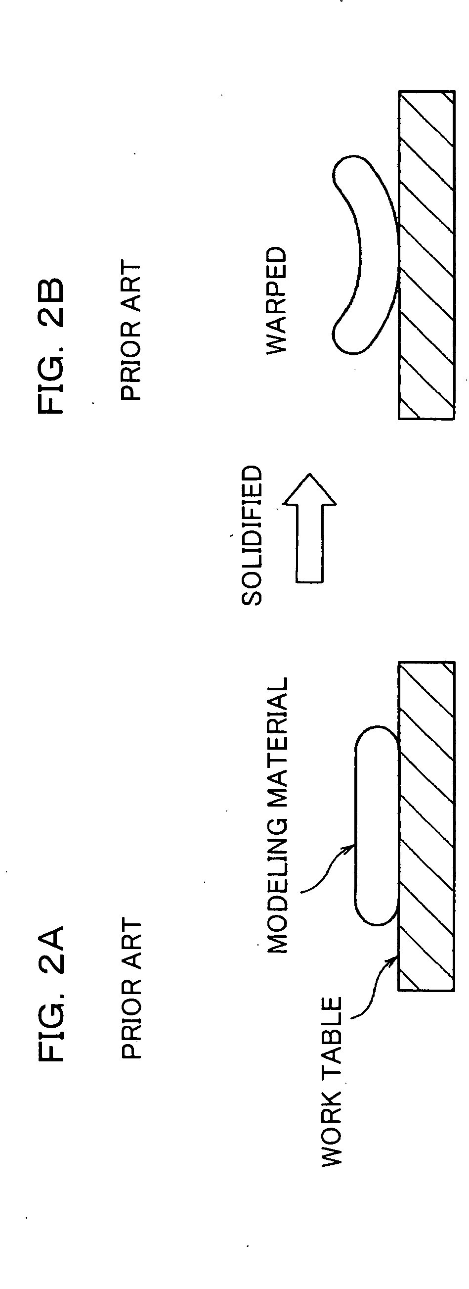
Meanwhile, according to a conventional pouring application method in which a large amount of modeling material is applied at the same time, since the large-volume modeling material is solidified at the same time, expansion and contraction at the time of the solidification considerably affect a 3D object to cause warpage in the completed 3D object (refer to FIG. 2B).
As a result, the quality of the completed 3D object deteriorates.

Method used


Image

  • 3D modeling device and 3D modeling method for supplying material with high precision
  • 3D modeling device and 3D modeling method for supplying material with high precision
  • 3D modeling device and 3D modeling method for supplying material with high precision

Examples


Embodiment Construction

[0029] An embodiment of a 3D modeling device and a 3D modeling method is described in detail with reference to the accompanying drawings hereinafter.

[0030]FIG. 3 is a schematic view showing a 3D modeling device according to one embodiment of the present invention. Referring to FIG. 3, the 3D modeling device 10 comprises a pair of support parts 12L and 12R which are extended vertically and have the shape of square pole, and a bottom part 12B which connects the support parts 12L and 12R, so that those parts form a U-shaped arm 12. In addition, the 3D modeling device 10 comprises a rail 14 provided at an upper part of the pair of support parts 12L and 12R, and a carriage 16 provided so as to be movable on the rail 14 within a predetermined range in the X-direction in a X-Y-Z orthogonal coordination system (refer to FIG. 3 showing the coordination system).

[0031] A spindle 28 is fixed to a head (refer to FIGS. 3 and 5) which is provided adjacent to the carriage 16 and movable within a ...


PUM

PropertyMeasurementUnit
melting pointaaaaaaaaaa
distanceaaaaaaaaaa

Abstract

A 3D modeling device performs repeatedly a step of cutting a subsidiary material layer formed of a subsidiary material and cutting a modeling material layer formed of a modeling material. The 3D modeling device comprises at least one of a subsidiary material supplying device which discharges the subsidiary material drop by drop from an outlet positioned apart from a region in which the subsidiary material is to be applied at a predetermined distance, and a modeling material supplying device which discharges the modeling material drop by drop from an output positioned apart from a region in which the modeling material is to be applied at a predetermined distance. Since the material can be applied with high precision, a high-quality 3D molded object is provided.

Description

BACKGROUND OF THE INVENTION [0001] 1. Field of the Invention [0002] The present invention relates to a 3D modeling device and a 3D modeling method and more particularly, it relates to a 3D modeling device and a 3D modeling method which makes a 3D object by depositing a subsidiary material layer formed of a subsidiary material and a modeling material layer formed of a modeling material. [0003] 2. Description of the Background Art [0004] Conventionally, when a desired 3D object is made of a modeling material such as a resin, the modeling material is applied linearly from a nozzle as shown in FIG. 1A or a large amount of modeling material is applied at the same time as shown in FIG. 2A. [0005] When a 3D object such as an almost triangle-shaped wall shown in FIG. 1B is made by a conventional linear application method in which a modeling material is applied from a nozzle linearly, for example, since the modeling material is applied from the nozzle linearly while the tip end of the nozzle...

Claims


Application Information

Patent Timeline
Patent Type & Authority Applications(United States)
IPC IPC(8): B29C67/00B29C35/08
CPCB29C67/0055B29K2705/00B29C67/0092B29C67/0059B29C64/106B29C64/112B29C64/40
Inventor OWADA, KOJI
Owner ROLAND DG CORP
Learn More