Back light unit with high heat transfer rate

a back light unit and heat transfer rate technology, applied in the field of back light units, can solve the problems of high temperature near the light tube, normal operation of the display panel, accumulation of heat generated during operation, etc., and achieve the effect of improving the heat transfer rate of the back light unit, high heat transfer rate, and effective improvement of the heat transfer ra

Active Publication Date: 2005-11-10
AU OPTRONICS CORP
View PDF4 Cites 15 Cited by
  • Summary
  • Abstract
  • Description
  • Claims
  • Application Information

AI Technical Summary

Benefits of technology

[0009] According to the claimed invention, a back light unit with a high heat transfer rate is disclosed. The back light unit disposed under a display panel comprises a light source generator, a diffusing plate positioned on the light source generator, and a reflecting sheet positioned underneath the light source generator for reflecting the generated light beams upward to the diffusing plate. The diffusing plate is used to diffuse the light beams in advance to provide a uniform light to the display panel. The reflecting sheet comprises at least one opening or an uneven structure to improve the heat transfer rate of the back light unit.
[0010] According to the claimed invention, the reflecting sheet in the back light unit comprises at least one opening or an uneven structure so as to improve the heat transfer rate effectively and avoid heat from accumulating in the light source generator nearby, so as to improve the display performance of the display panel and lengthen the lifetime of devices.

Problems solved by technology

Thus, the heat generated during operation accumulates rapidly, leading to a high temperature near the light tubes after operating for a period of time.
The high temperature interferes with the normal operation of the display panel 12 and deteriorates the display performance.
For example, distortion easily occurs on the screen.
This leads to a decrease in the lifetime of devices nearby.

Method used


Image

  • Back light unit with high heat transfer rate
  • Back light unit with high heat transfer rate
  • Back light unit with high heat transfer rate

Examples


Embodiment Construction

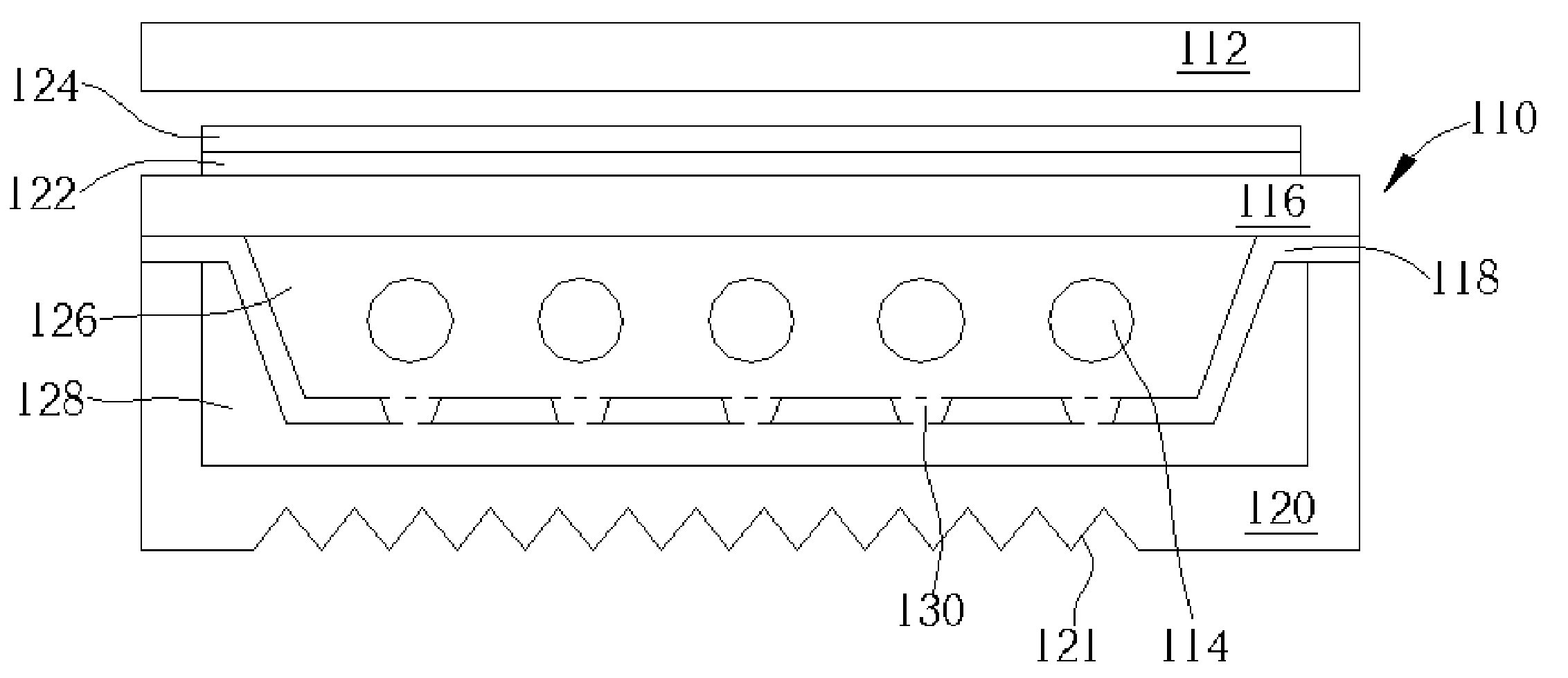
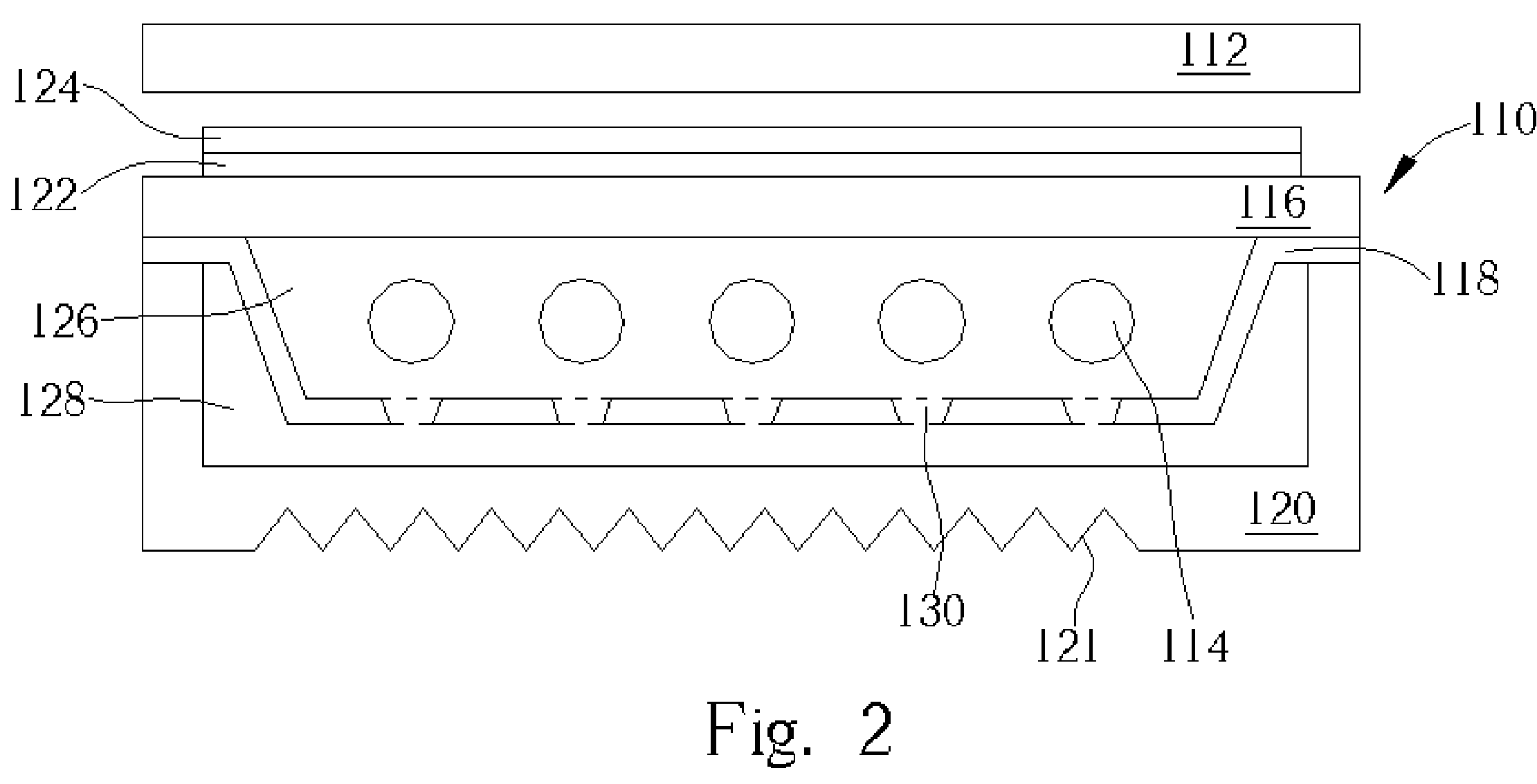
[0018] Please refer to FIG.2 of a cross-sectional diagram of a back light unit 110 according to a first embodiment of the present invention. As shown in FIG.2, the back light unit 110 is installed underneath a display panel 112 and comprises a diffusing plate 116, a reflecting sheet 118 disposed under the diffusing plate 116, and a light source generator 114 in a chamber 126 surrounded by the diffusing plate 116 and the reflecting sheet 118. In the preferred embodiment of the present invention, the back light unit 110 further comprises a housing 120 installed under the reflecting sheet 118 and surrounding the reflecting sheet 118 to form a chamber 128.

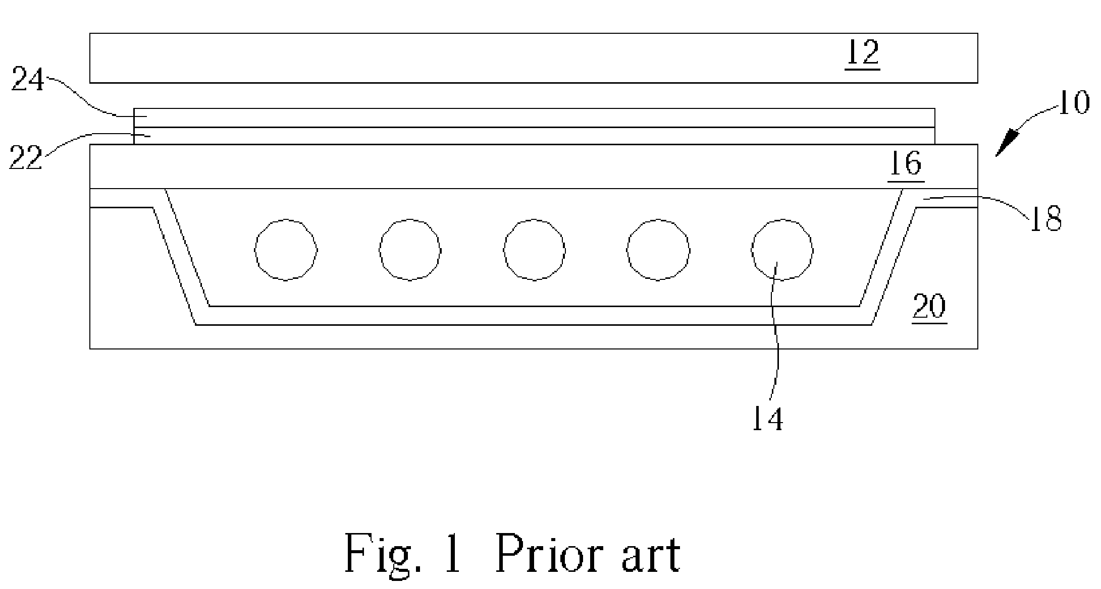
[0019] As the aforementioned description of the conventional back light unit 10, the light source generator 114 is similarly composed of a plurality of light tubes. There is no limitation in the types, shapes, and the arranged method of the light tubes. In the first preferred embodiment of the present invention, the light source gener...


PUM

PropertyMeasurementUnit
heat transfer rateaaaaaaaaaa
shapeaaaaaaaaaa
widthaaaaaaaaaa

Abstract

A backlight unit with high heat transfer rate disposed under a display panel. The backlight unit includes a light source generator for generating light beams, a diffusing plate positioned between the light source generator and the display panel for scattering the light beams to the display panel, and a reflecting sheet position under the light source generator for reflecting the light beams upward. The reflecting sheet has at least one opening for increasing the heat transfer rate of the backlight unit.

Description

BACKGROUND OF INVENTION [0001] 1. Field of the Invention [0002] The present invention relates to a back light unit of a display panel, and more particularly, a back light unit having a high heat transfer rate. [0003] 2. Description of the Prior Art [0004] A back light unit, which is a key element in the fabrication of liquid crystal displays, is widely used in digital cameras, PDAs, vehicle satellite navigation systems, computer monitors, flat panel TVs, and so on. Typically, a back light unit, which is generally installed underneath a display panel, comprises a light source (or multiple light sources) and a light diffusion plates for providing users with diffused and uniform light beams. Light beams penetrate the overlying display panel and form various images controlled by pixel electrodes densely arranged on the display panel. Back light units are typically divided into two major categories: direct-type, in which the light source is generated form underneath the display panel dir...

Claims


Application Information

Patent Timeline
Patent Type & Authority Applications(United States)
IPC IPC(8): F21S8/00F21V29/00F21V29/505G02F1/13357G09F13/04G09F13/14H01K1/62
CPCF21S8/00F21S48/328F21V29/004F21Y2103/00F21V29/83G09F13/04G09F13/14F21V29/74G02F2001/133628G02F1/133628
Inventor HSIEH, CHIN-KUNYU, CHUAN-PEILIU, HAN-CHOU
Owner AU OPTRONICS CORP
Why Eureka
Try Eureka