Methods of pulsed nuclear energy generation using piston-based systems

a technology of pulsed nuclear energy and piston-based systems, which is applied in the direction of marine propulsion, vessel construction, greenhouse gas reduction, etc., can solve the problem of high power production per volume of engine, and achieve the effect of high heat transfer rate, high heat transfer coefficient and high surface heat exchang

Inactive Publication Date: 2013-01-03
MAYBURD ANATOLY
View PDF0 Cites 15 Cited by
  • Summary
  • Abstract
  • Description
  • Claims
  • Application Information

AI Technical Summary

Benefits of technology

[0025]An advantage of the invented system is high heat transfer coefficient on the heating end due to vigorous convection and high surface of heat exchange between the bubbles of forming steam and yet non-boiling working fluid. High heat transfer rate leads to high rate of power production per volume of the engine.
[0031]Still another advantage is the ability to extract useful energy in short powerful pulses, achieving high power-per-mass ratio.

Problems solved by technology

High heat transfer rate leads to high rate of power production per volume of the engine.

Method used


Image

  • Methods of pulsed nuclear energy generation using piston-based systems
  • Methods of pulsed nuclear energy generation using piston-based systems
  • Methods of pulsed nuclear energy generation using piston-based systems

Examples


embodiment 1

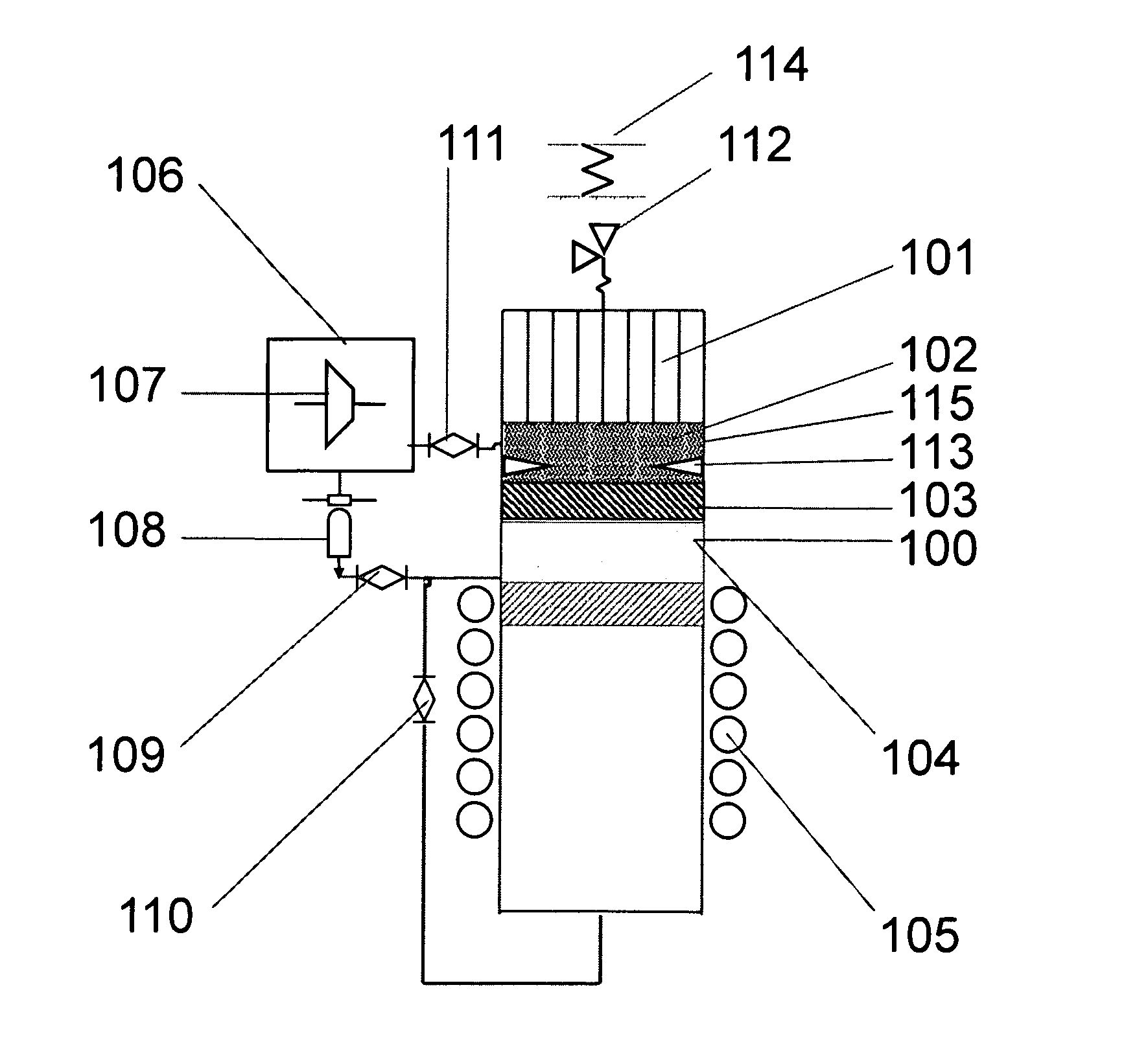
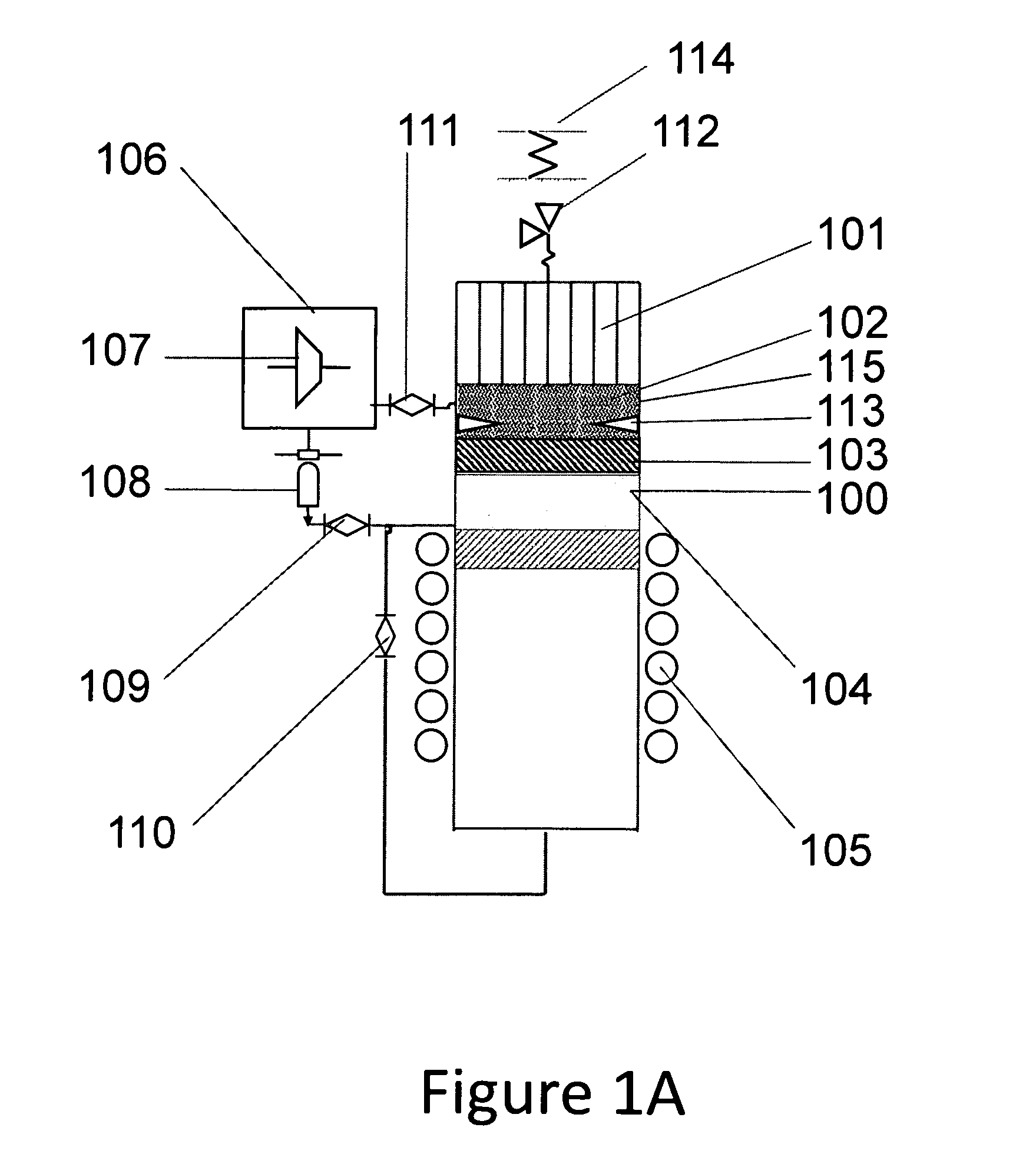
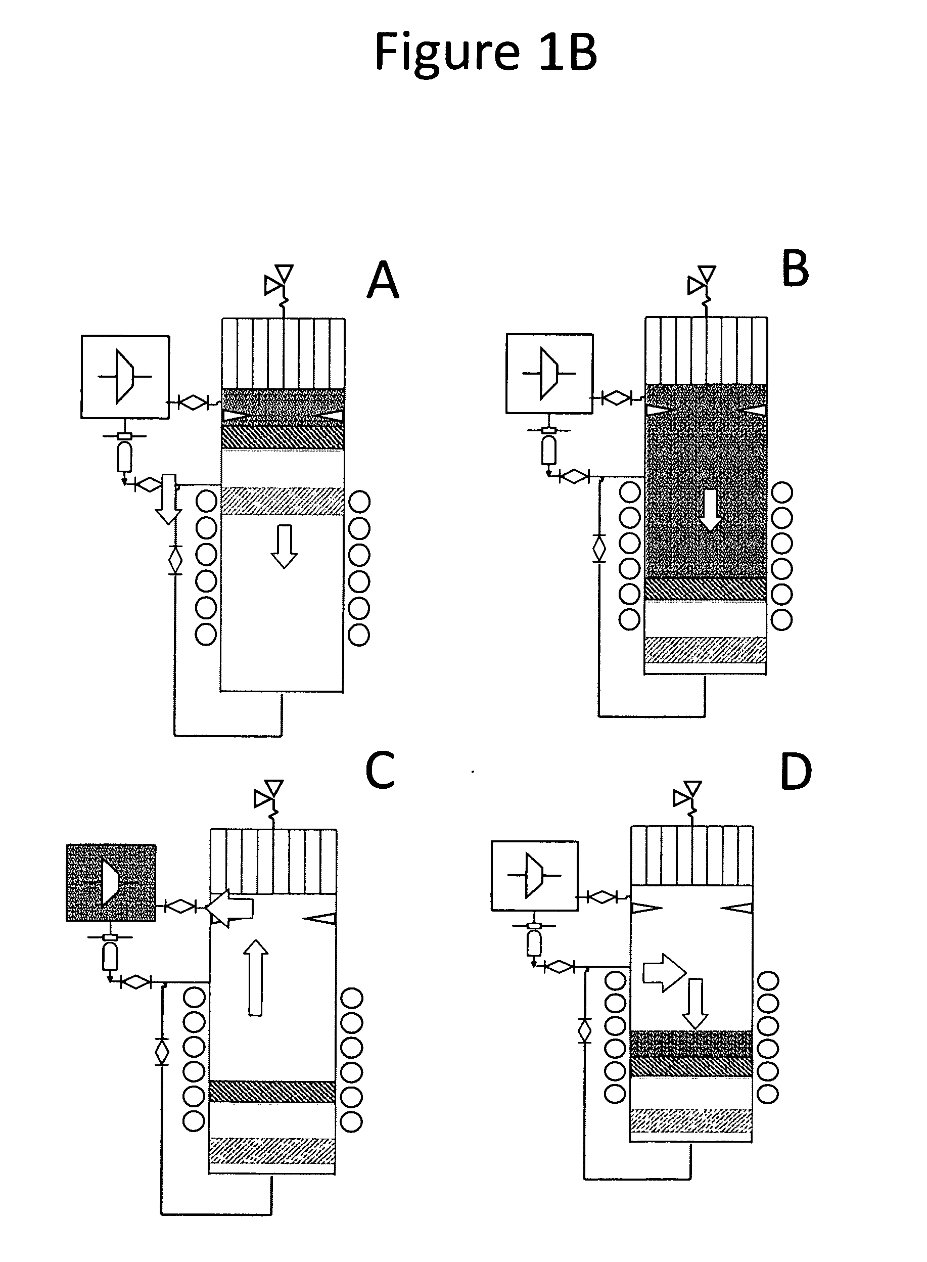
[0045]In the embodiment 1 according to FIG. 1A, the system comprises the heating element 101, metallic or ceramic cylinder 100 housing the heating element 101 on its “hot end”, “cold end”, opposite to the hot end, piston 103, beryllium neutron reflectors 104, electromagnetic alternator 105, condenser 106, a turbo-expander 107, fluid accumulator with an optional heat-exchanger 108, an exhaust valve 111, an inlet valve 109, a drain valve 110, a safety valve 112, piston restrictors 113, shock absorbers 114. Other elements known in the art are not shown but will be discussed when necessary. Relative to the direction of gravity force, the heating zone is on the top of the cylinder and the piston approaches it from below to trigger a new cycle. The reason for such orientation of the heaters is thermodynamic efficiency. This parameter will be improved if the entire mass of the condensed moderator is introduced in the heating zone and thus creates a small volume of high pressure steam. Plac...

embodiment 2

[0053]FIG. 3.A presents the parts of the embodiment 2. 101 is the nuclear heat source, 209 is inner reaction vessel, 208 is working space, occupied by vapors of the water-immiscible working fluid (pentane, butane), condenser 204. The parts 205, 206, 207 are parts of a low-density floating piston, lighter than water 210 but heavier than working fluid 211, with a layer of neutron reflector 207 built in and located in horizontal plane, 205 being a heat-insulating light-weight material and 206 being a structural plate. 203 is a hydraulic turbine, 201 is an annular reservoir, a ceramic water impervious construct coaxial and in hydraulic contact with 209.

[0054]The gas expansion caused by the evaporation brings into motion a column of water through a hydraulic turbine (FIG. 3B, stage A). The turbine is rotated again when the evaporated steam is condensed and the water levels off, taking the starting position (FIG. 3B, stage B). The attractive side of the process is its simplicity, and econ...

embodiment 3

[0057]FIG. 4A shows the parts of the embodiment 3 also termed “steam gun”. In this approach the system comprises (FIG. 4A) the heating element 101, metallic or ceramic cylinder 100 housing the heating element 101 on its “hot end”, “cold end”, opposite to the hot end, piston 103, beryllium neutron reflectors 104, electromagnetic alternator 105, a drain valve 110, a safety valve 112, piston restrictors 113, shock absorbers 114. Other elements known in the art are not shown but will be discussed when necessary. Relative to the direction of gravity force, the heating zone is on the top of the cylinder and the piston approaches it from below to trigger a new cycle. The element 301 (condensation space) differentiates this embodiment with the embodiment 1 as well as the absence of the valves 109 and 110. The gas expansion proceeds in four steps: a) evaporation of working fluid b) overheating c) adiabatic expansion until saturation d) isentropic expansion of the saturated vapor in the same ...


PUM


Abstract

The invention describes a method of nuclear energy transformation into electric and / or mechanical energy by triggering criticality in a working cylinder by an approach of a piston with a neutron reflector layer to fissile heat elements. Optionally, liquid moderator should fill the heating element to provide for an additional condition of such triggering. The pulse reaction initiates a heat cycle by expanding working fluid, extracting mechanical work and compressing the working fluid using lower amount of energy. The energy released in reaction can drive a column of water as a liquid piston propelling a highly efficient hydraulic turbine and producing a simple economical method of energy conversion. The piston movements can also be converted in laser and electromagnetic pulses. Self-regulation of nuclear reaction by a reflector piston linked to a resilient spring can be used in marine propulsion. In one method, the approach of the reflector piston triggers a reaction that evaporates water in the pressure chamber and produces a reactive thrust in a noozle. A fraction of the steam is diverted to produce steam bubble envelope on the surface of the vessel to minimize drag. Another fraction of the diverted steam drives a pump, pumping sea water into the heating elements. Other practical and novel applications of the method are disclosed.

Description

FEDERALLY SPONSORED RESEARCH[0001]not applicableSEQUENCE LISTING OR PROGRAM[0002]not applicable\FIELD OF INVENTION[0003]This invention belongs to the field of peaceful nuclear energy conversion and introduces novel engines operating on nuclear energy.BACKGROUND[0004]A group of technological processes and human activities was always important and gains even more significance recently: mining of mineral riches and fossil fuels, mining production of non-oil fossil fuels, drilling exploration of sea bed, ground drilling operations on dry surface, sea water desalination, fluid pumping, general energy production, marine, river and rail propulsion, non-rail propulsion on dry surface, space propulsion, unmanned flight, residential heating, energy provision of military bases, pulse production of energy for lasers, pulse production of energy for particle accelerators, pulse production of energy for charging super-capacitors.[0005]Under many circumstance performing these operations efficiently...

Claims


Application Information

Patent Timeline
Patent Type & Authority Applications(United States)
IPC IPC(8): B63H1/00F02G1/055B63B1/34
CPCG21D7/00Y02E30/00
Inventor MAYBURD, ANATOLY L.
Owner MAYBURD ANATOLY
Why Eureka
Try Eureka