Electrical heating method for a hydrocarbon formation, and improved thermal recovery method using electrical pre-heating method

a hydrocarbon and heating method technology, applied in the field of electric heating methods for hydrocarbon formations, to achieve the effect of improving the mobility of oil

Inactive Publication Date: 2014-09-04
HUSKY OIL OPERATIONS
View PDF3 Cites 18 Cited by
  • Summary
  • Abstract
  • Description
  • Claims
  • Application Information

AI Technical Summary

Benefits of technology

[0011]As noted above under “Field of the Invention” herein, the invention in one aspect thereof relates to an electrical pre-heating step for heating oil within a form

Problems solved by technology

As further explained below, the inventor has discovered that such prior art heating method of heating to constant temperature at the magnetic induction heating elements fails to optimize heating (and thus conform subsequent steam chamber development)

Method used


Image

  • Electrical heating method for a hydrocarbon formation, and improved thermal recovery method using electrical pre-heating method
  • Electrical heating method for a hydrocarbon formation, and improved thermal recovery method using electrical pre-heating method
  • Electrical heating method for a hydrocarbon formation, and improved thermal recovery method using electrical pre-heating method

Examples


example 1

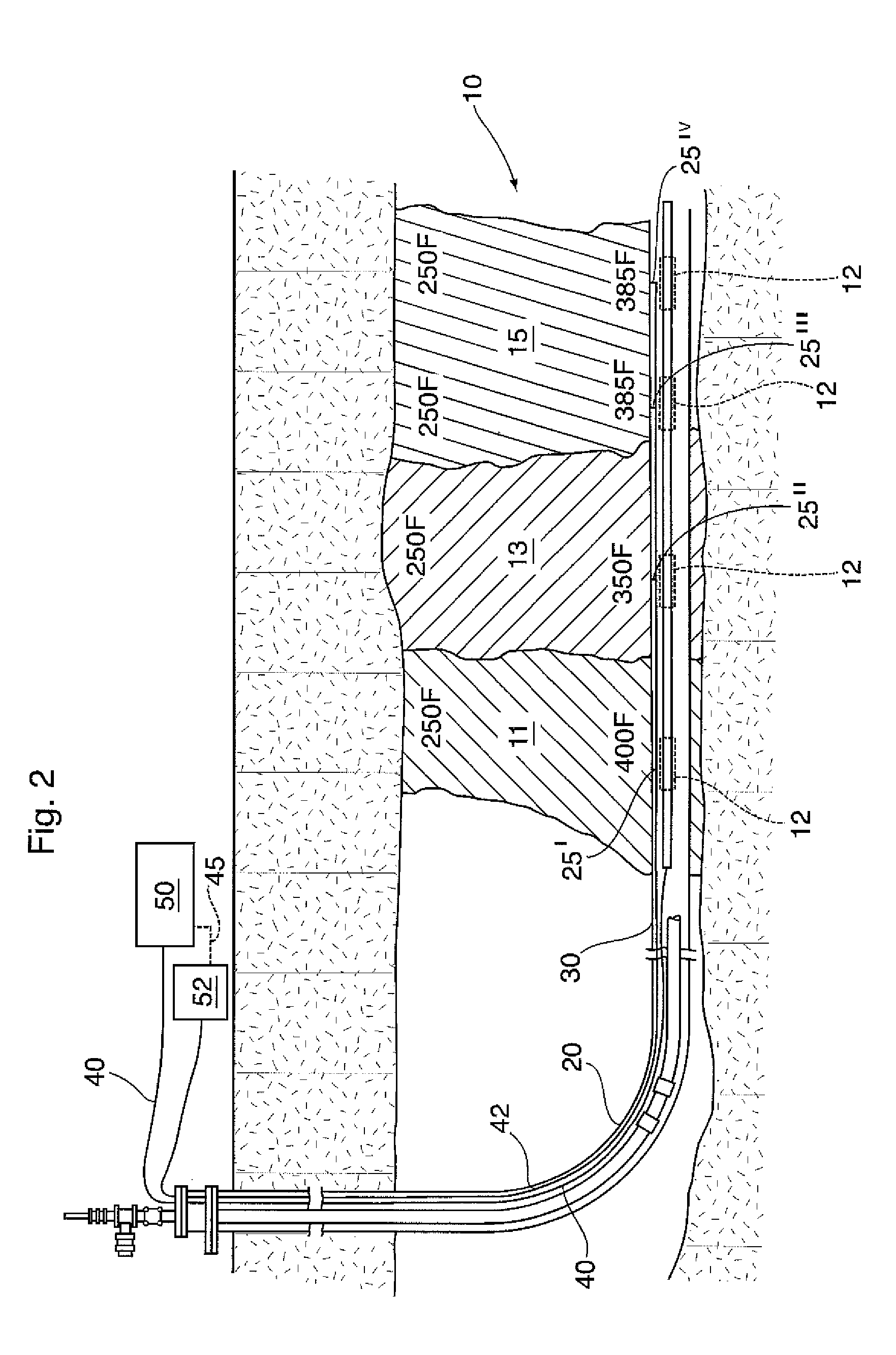
[0101]In order to confirm the positive impact of the method of the present invention, and in particular the more extensive temperature conformity throughout various regions of a non-homogenous formation for SAGD operations for which an electrical pre-heating step has been conducted, a sample formation was modelled, using the computer numerical simulation of the STARS™ Thermal Simulator 2010.12 provided by the Computer Modelling Group, Calgary, Alberta, Canada.

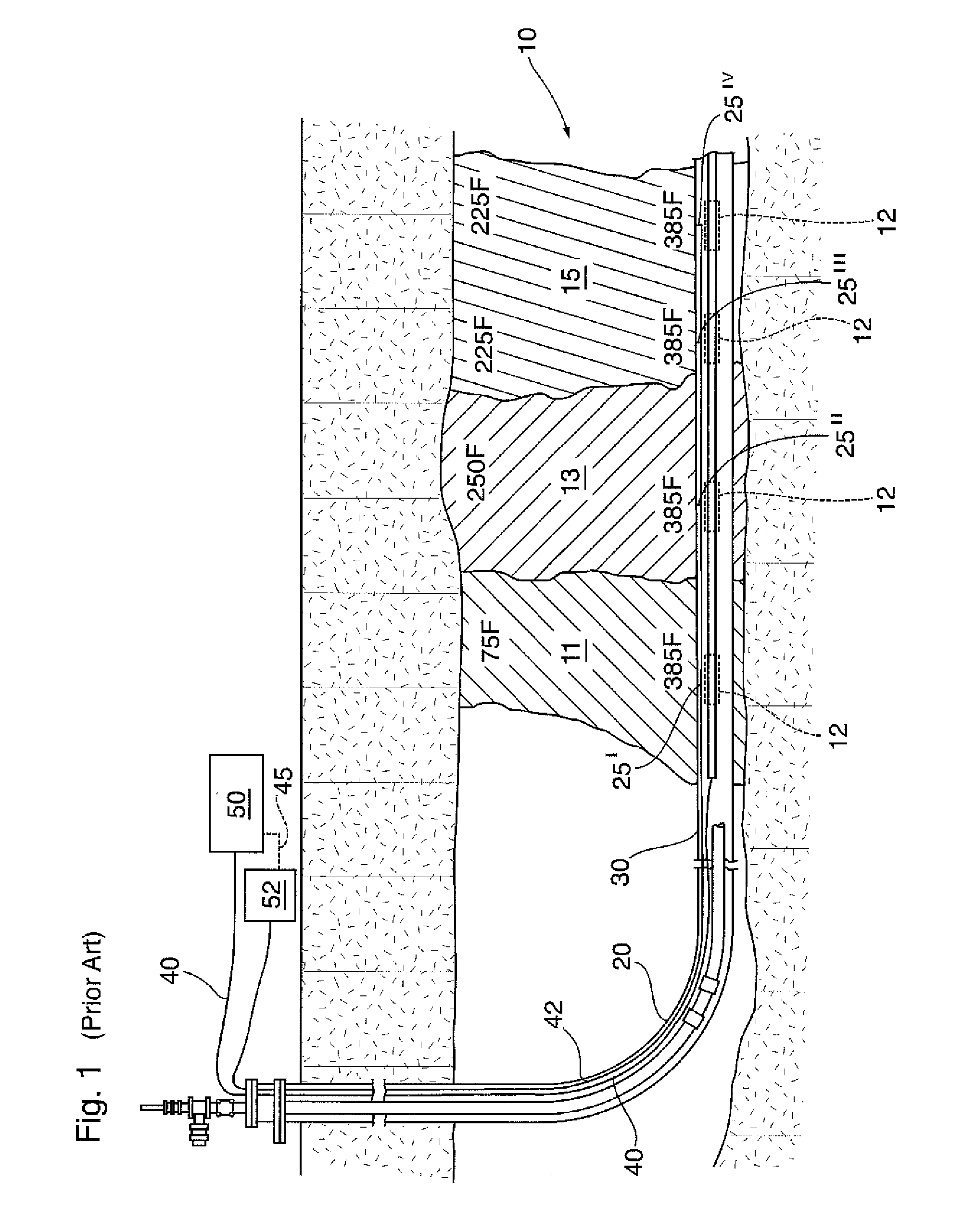
[0102]The modelling reservoir used in Examples 1 &2 herein contained bitumen at 7° C., with uniform porosity (30%), but comprising three (3) distinct and separate areas 11, 13, and 15 as shown in FIGS. 1-6 herein, such regions and formation 10 having properties as shown in Table 1 below, and in particular containing, as shown in Table 1 below, initial water saturation at the heel of 7% (i.e. region 11), mid-well initial water saturation of 22% (i.e. in region 13), and initial water saturation at the toe of 15% (i.e. in region 1...

example 2

[0110]The same formation was modelled with two similar wells 20, 70, but with electrical heating instead of steam circulation. Such electrical heating was carried out in accordance with the prior art methods of maintaining constant temperature along the wellbores.

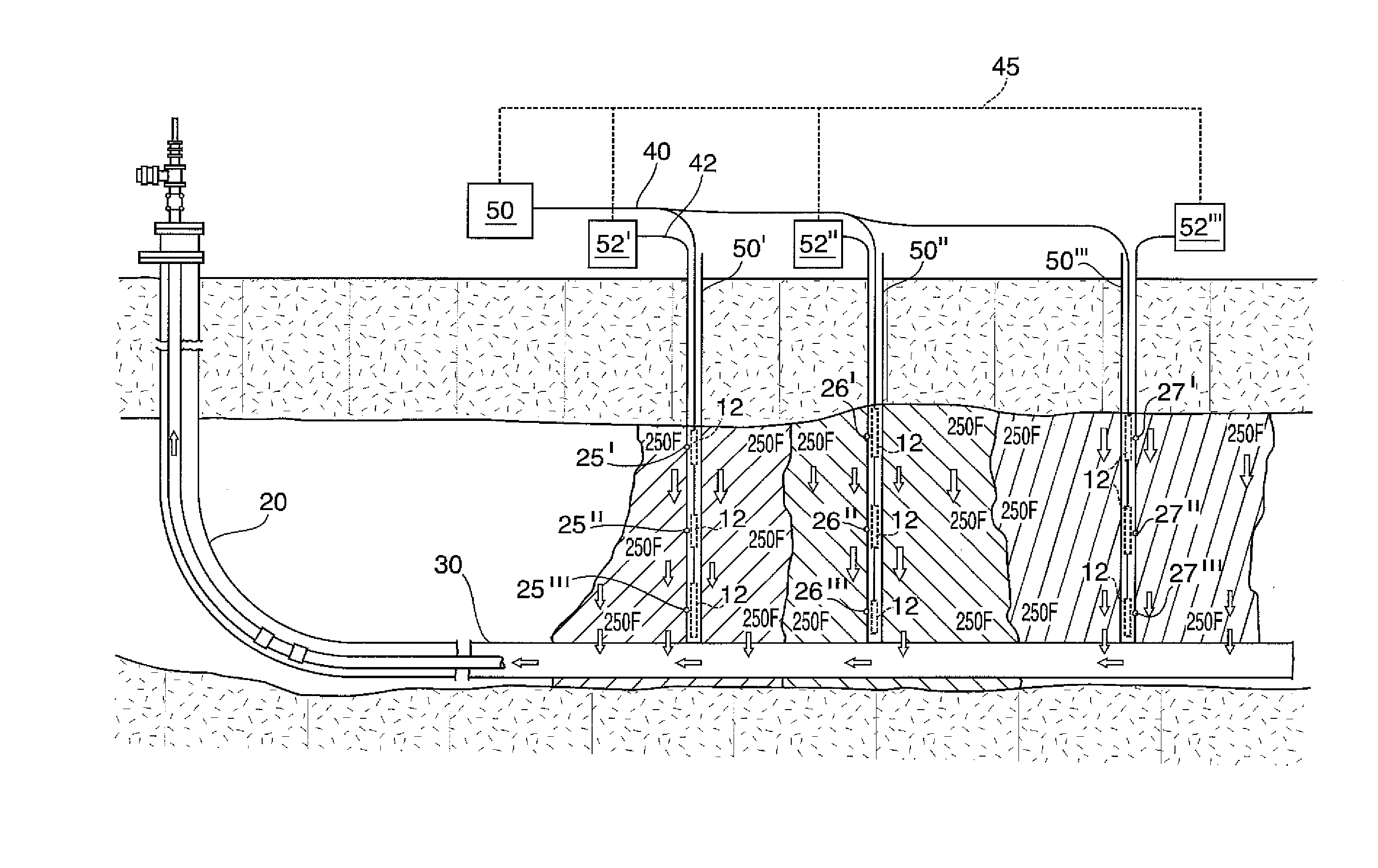
[0111]In this regard, the same well pair 20 and 70 were used, with three electrical heating elements 12 inserted in each of wells 20 and 70 as shown in FIG. 6, for heating respectively the three distinct regions 11, 13, and 15.

[0112]FIG. 12 shows, with reference to the temperature correlation grid on the right hand side, the temperature distribution within the 3 regions of the modelled formation having electrical heating within both of wells 20, 70, after 1 month.

[0113]FIG. 13 shows, with reference to the temperature correlation grid on the right hand side, the temperature distribution within the 3 regions of the modelled formation having electrical heating of such 3 regions from both of wells 20, 70, after 2 months.

[0114]F...

example 3

[0116]In this example the same formation was modelled with two similar wells 20, 70, but with optimized electrical pre-heating of each of the three regions 11, 13, and 15 in accordance with the method of the present invention.

[0117]Specifically, electrical heating was carried out with a maximum target temperature of 400° C. in respect of region 11, a temperature of 50° C. in respect of region 13 (i.e. no heating), and a target temperature of 300° C. in respect of region 15.

[0118]FIG. 16 shows, with reference to the temperature correlation grid on the right hand side, the temperature distribution within the 3 regions 11, 13, and 15 of the modelled formation having such optimized electrical heating of such 3 regions within both of wells 20, 70, after 3 months.

[0119]FIG. 17 shows, with reference to the temperature correlation grid on the right hand side, the temperature distribution within the 3 regions of the modelled formation after three (3) months of optimized electrical pre-heatin...


PUM


Abstract

A thermal recovery method employing an electrical pre-heating method to condition the hydrocarbon-bearing formation as a means of improving recovery when steam injection is later applied. In addition, a method of comparing the applied electrical flux and resulting temperature profile to determine the heat transfer properties of each of a plurality of reservoir regions along the length of a horizontal well is disclosed. Advantageously, the heat flux supplied to each of the regions may be varied relative to each other region to compensate for different thermal transfer properties which may exist in the formation within each of the regions. Such controlled variation in thermal energy transfer, compensating for variances in fluid mobility and thermal properties in the reservoir allows for a more even steam chamber development and therefore optimized oil recovery.

Description

FIELD OF THE INVENTION[0001]The invention relates to an improved thermal recovery method employing an electrical pre-heating method to condition a hydrocarbon-bearing formation as a means of improving recovery when steam injection is later applied. The invention also relates to an improved (optimized) method per se of electrically heating oil in a formation.BACKGROUND OF THE INVENTION AND DESCRIPTION OF THE PRIOR ART[0002]Each of U.S. Pat. No. 6,612,808 and similar corresponding PCT application WO 1998 / 058156, each to Isted, R. E., entitled “Method and Apparatus for Subterranean Thermal Conditioning” and “Method and Apparatus for Subterranean Magnetic Induction Heating”, respectively, teach a method and apparatus for heating oil in a hydrocarbon-containing formation using magnetic induction heating elements to thereby mobilize oil within the formation for subsequent gravity drainage. No subsequent steam heating is disclosed.[0003]Moreover, with regard to the manner of electrical hea...

Claims


Application Information

Patent Timeline
IPC IPC(8): E21B43/24
CPCE21B43/2406E21B43/2401E21B43/2408E21B47/07
Inventor WOLLEN, CODY
Owner HUSKY OIL OPERATIONS
Why Eureka
Try Eureka