Flat light source device

Inactive Publication Date: 2005-11-10
MITSUBISHI RAYON CO LTD
View PDF2 Cites 26 Cited by
  • Summary
  • Abstract
  • Description
  • Claims
  • Application Information

AI Technical Summary

Benefits of technology

[0008] Therefore, an object of the present invention is to provide a planar light source device which enhances

Problems solved by technology

Additionally, since a polarization direction of light emitted from the backlight unit has heretofore been uneven, about half of the light has Seen absorbed and wasted by a polarization plate disposed on an incidence side of the liquid crystal display unit.
However, in actuality, since there occurs a loss of quantity of light every time the light reflected by the polarization se

Method used


Image

  • Flat light source device
  • Flat light source device
  • Flat light source device

Examples


Example

Comparative Example 1

[0075] A light guide whose one major surface was a mat-finished surface having an average inclination angle of 2.5° and whose other major surface was a mirror surface was prepared by injection molding using an acrylic resin (Acripet VH5#000 manufactured by Mitsubishi Rayon Co., Ltd.). The light guide had a wedge plate shape having a size of 216 mm×290 mm and having a thickness changing to 2.0 mm-0.7 mm along the side (short side) having a length of 216 mm. A prism layer was formed of an acrylic ultraviolet setting resin in which elongated prisms each having a prism apex angle of 100° were juxtaposed and arranged at a pitch of 50 μm in parallel with the short side of the light guide on the mirror surface side of the light guide. A cold cathode tube was disposed along one side end face (end face on the side having a thickness of 2.0 mm) corresponding to a side (long side) of the light guide having a length of 290 mm. The cold cathode tube was covered with a light...

Example

EXAMPLE 1

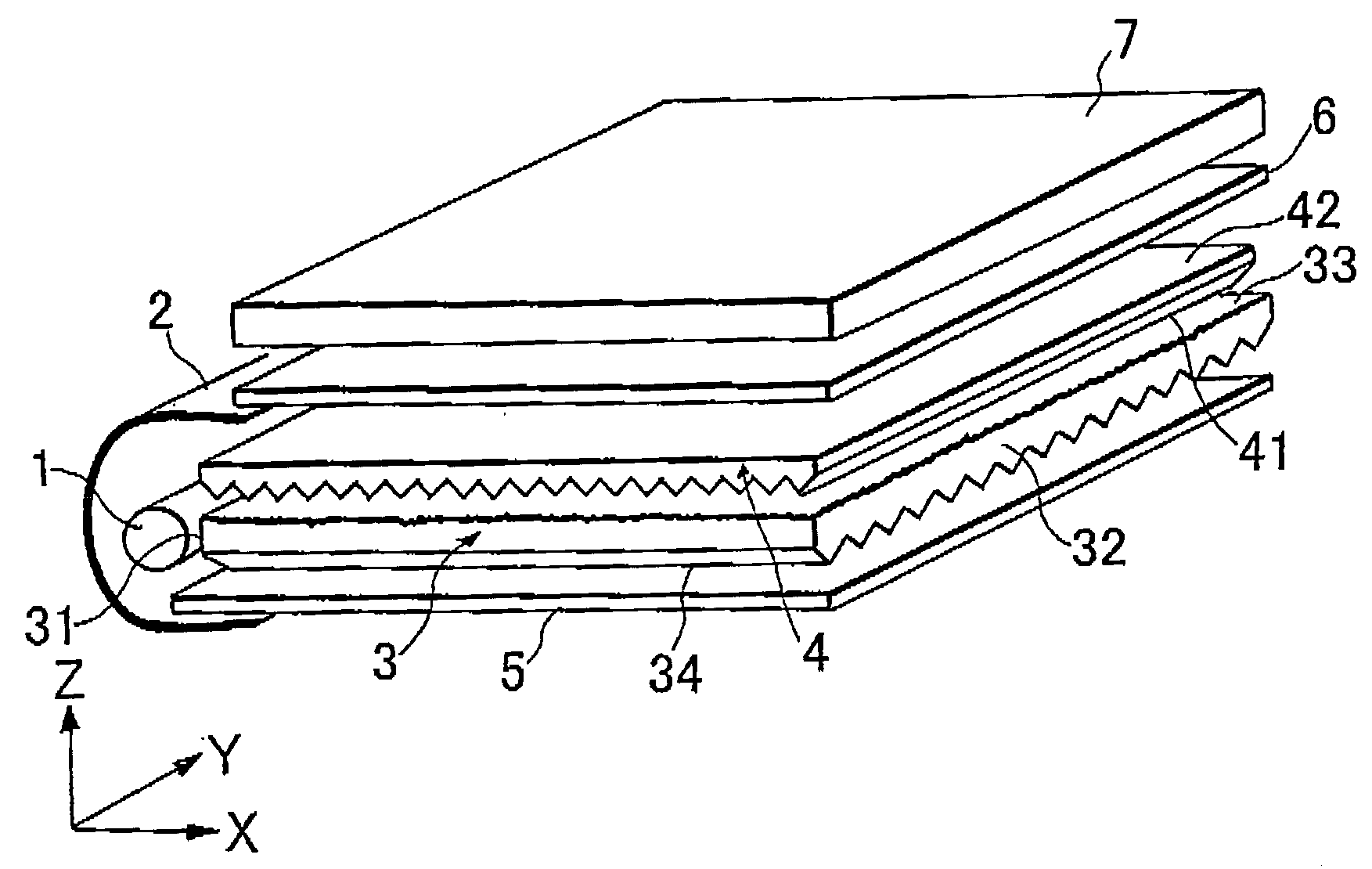
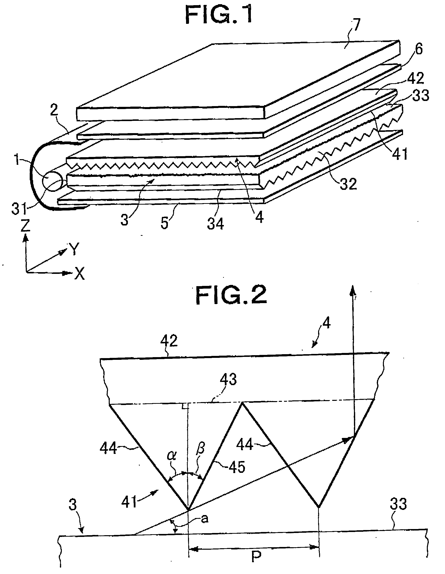
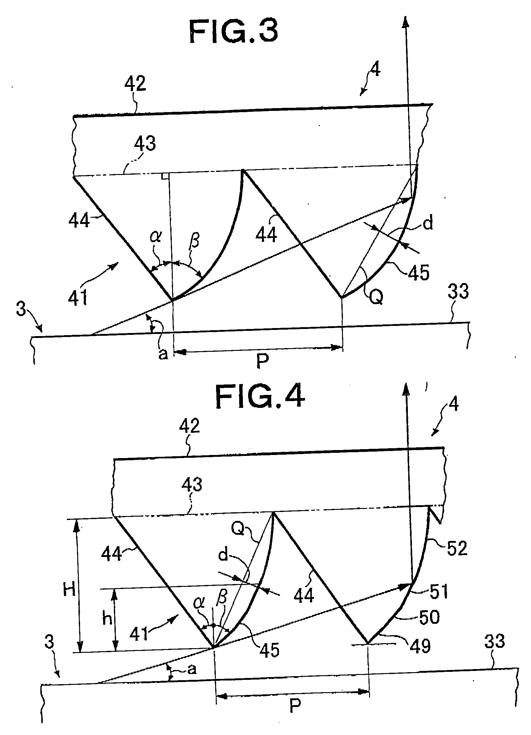
[0080] A planar light source device was prepared in the same method as that of Comparative Example 1 except that the following was used as a light deflection element 4.

[0081] A prism sheet in which an elongated prism formed surface was formed on one surface of a polyester film having a thickness of 125 μm was prepared using an acrylic ultraviolet ray setting resin having a refractive index of 1.5064. On the elongated prism formed surface, elongated prisms were substantially juxtaposed and arranged at a pitch of 56.5 μm. One prism face (first prism face) constituting the elongated prism was a flat face having an angle (α) of 32.5° formed with a normal line. The other prism face (second prism face) comprised two convex curved faces: a convex curved face (inclination angle=56.60, β=33.8°) extending through an area of elongated prism height of 0 (a prism apex portion) to 21.4 μm from a prism apex portion and forming a part (vicinity of a portion having a curvature radius of 8...

Example

EXAMPLE 2

[0083] A planar light source device was prepared in the same method as that of Comparative Example 1 except that the following was used as a light deflection element 4.

[0084] A prism sheet was prepared in the sane manner as in Example 1 except that a second prism face constituting the elongated prism comprised seven flat faces: a flat face (β=34.8°) having an inclination angle of 55.2° and extending through an area of elongated prism height of 0 (a prism apex portion) to 16 μm from a prism apex portion; and six flat faces extending through another area of the elongated prism height of 16 μm or more from a prism apex portion and each having inclination angles of 55.5°, 56.2°, 57.0°, 57.8°, 58.4° and 59.4°, respectively, form a side close to the prism apex portion and an equal width. A ratio (d / P) of a maximum distance (d) from a virtual flat plane of the second prism face of the prism sheet with respect to a pitch (P) of the elongated prisms was 1.10%.

[0085] As to the obt...


PUM


Abstract

A planar light source device includes a primary light source (1), a light guide (3) which leads the light emitted from the primary light source (1), and having a light incident face (31) to which the light emitted from the primary light source (1) comes in, and a light emitting face from which the led light goes out, a light deflection element (4) arranged adjacent to the light emitting face (33) of the light guide (3), and a polarization separation element (6) disposed on the side of a light outgoing surface (42) of the light deflection element (4), and having a function of transmitting one of polarization components of the incident light and reflecting the other of the polarization components. The full width at half maximum of the luminance distribution of the incident light Upon the polarization separation element (6) in an XY plane parallel to the travel direction of the light in the light guide (3) is 25° or less. The reference symbol 7 indicates a liquid crystal display element.

Description

TECHNICAL FIELD [0001] The present invention relates to an edge light system planar light source device constituting a liquid crystal display device or the like for use as a display unit in a notebook-size personal computer, liquid crystal television, cellular phone, portable information terminal (personal digital assistants [PDA]) or the like, particularly to improvement of a planar light source device using a polarization separation element. BACKGROUND ART [0002] In recent years, color liquid crystal display devices have been broadly used as monitors for portable notebook-size personal computers, personal computers and the like, or as display units for liquid crystal television sets, video integrated liquid crystal television sets, cellular phones, portable information terminals and the like in various fields. With an increase of an information processing amount, diversification of needs, adaptation to multimedia and the like, enlargement of a screen, and enhancement of definition...

Claims


Application Information

Patent Timeline
IPC IPC(8): F21V8/00G02B5/30G02B6/00G02F1/13357
CPCG02B5/30G02B6/002G02F1/133615G02B6/0053G02B6/0056G02B6/0038G02F1/1335G02B6/0001
Inventor YAMASHITA, TOMOYOSHIHAYASHI, YASUKO
Owner MITSUBISHI RAYON CO LTD
Why Eureka
Try Eureka