
Data rate shifting methods and techniques

a data rate and rate shifting technology, applied in the field of communication, can solve the problems of packet loss due to collisions, packets to become corrupted, and difficult to operate the link at higher data rates, and achieve the effect of reducing throughpu

Inactive Publication Date: 2005-11-10
CISCO TECH INC
View PDF16 Cites 77 Cited by
  • Summary
  • Abstract
  • Description
  • Claims
  • Application Information

AI Technical Summary

Benefits of technology

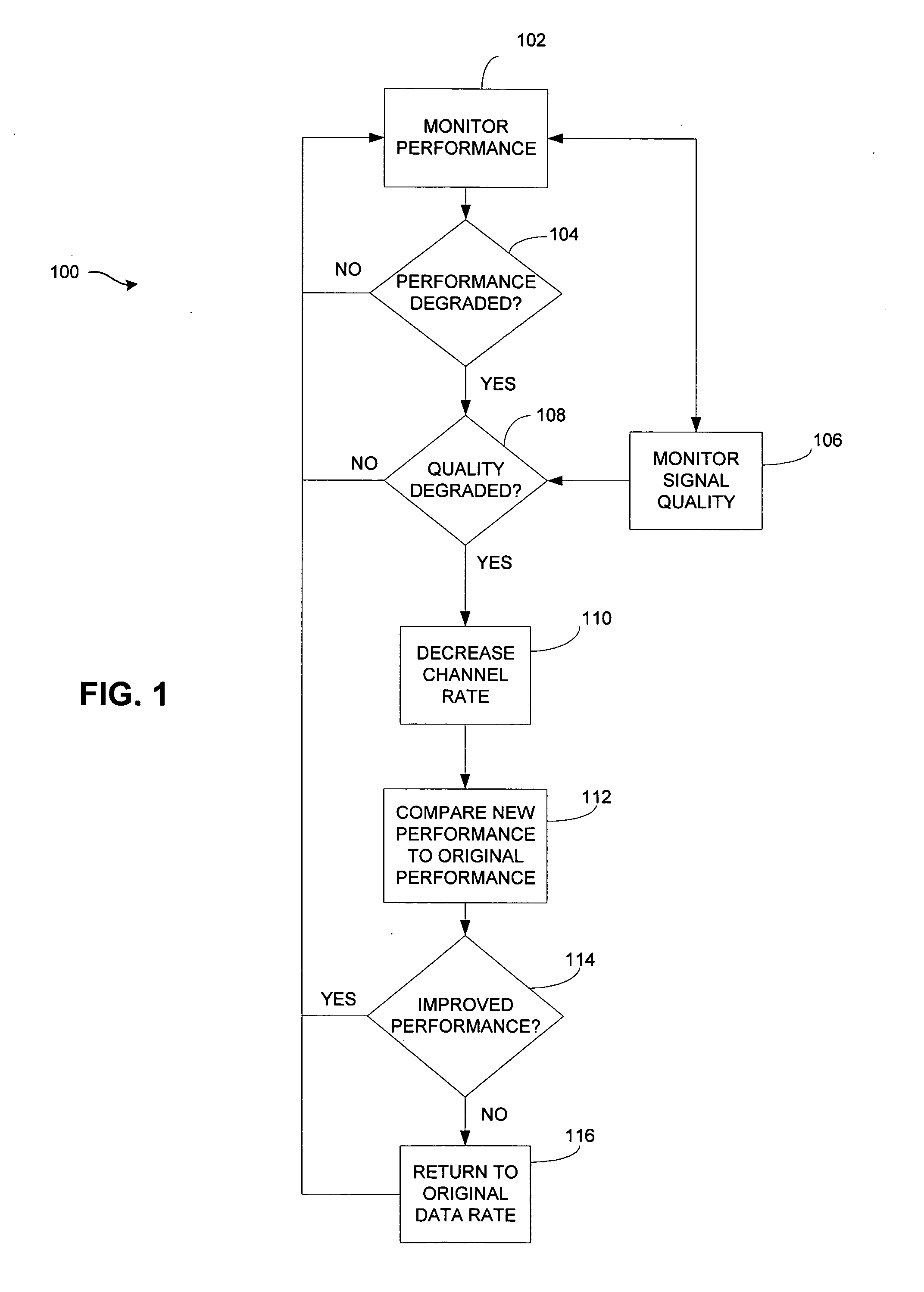
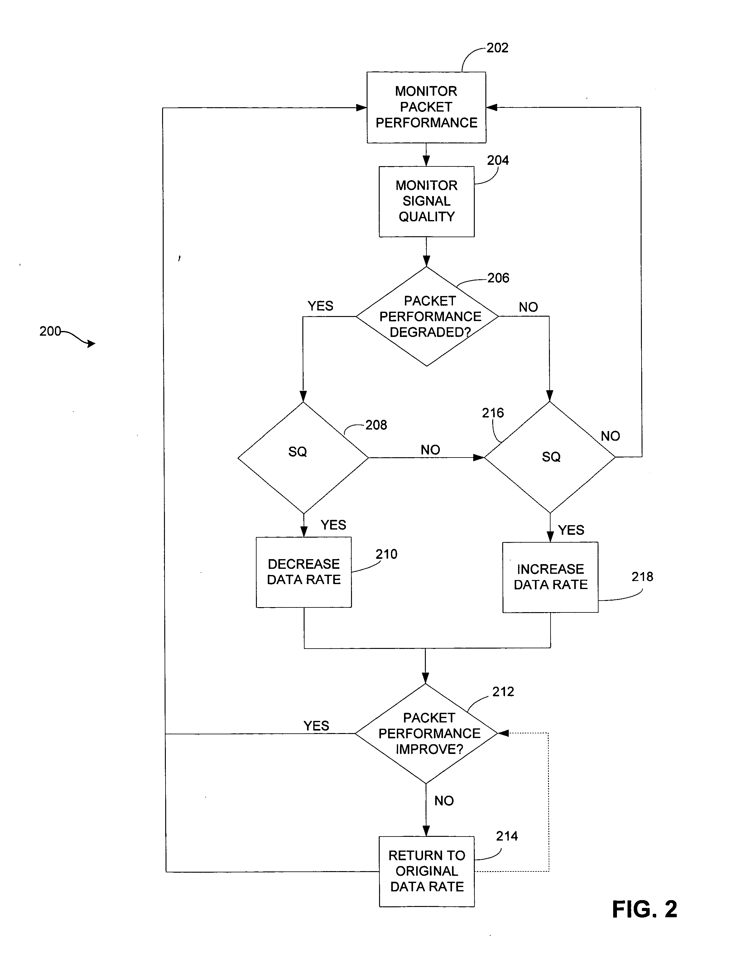
The present invention is about a technique for optimizing communication by distinguishing between packet loss due to poor signal quality and packet loss due to collisions with a large number of clients. The invention uses signal strength, quality, channel quality, packet loss rate, and throughput to make this distinction. The invention also includes a method for switching to a lower data rate when the performance parameter indicates a decrease in performance and a corresponding degradation of signal quality. The invention can also compare the packet loss rate with the history of the packet lost rate and switch to a higher data rate if the packet loss rate does not improve by a predetermined threshold. The invention can be implemented in communication devices that measure packet loss rate and monitor channel quality, and can adjust the data rate accordingly. The technical effects of the invention include improved communication efficiency and reduced data loss.

Problems solved by technology

As the link is degraded it becomes increasingly difficult to operate the link at higher data rates because corrupted packets and the subsequent retries consume much of the available bandwidth.
However, a problem with this technique is that packet loss due to collisions are interpreted the same as packet loss due to a poor channel, interference, or large amounts of noise.
Packet collisions within the network under normal operation with large numbers of clients and heavy traffic load can also cause packets to become corrupted.
If the packet loss is due to collisions, then rate shifting to a reduced data rate is not effective and may severely reduce network performance since lower data rates increase a packet's transmission time and therefore its collision probability.

Method used


Image

  • Data rate shifting methods and techniques
  • Data rate shifting methods and techniques
  • Data rate shifting methods and techniques

Examples


Embodiment Construction

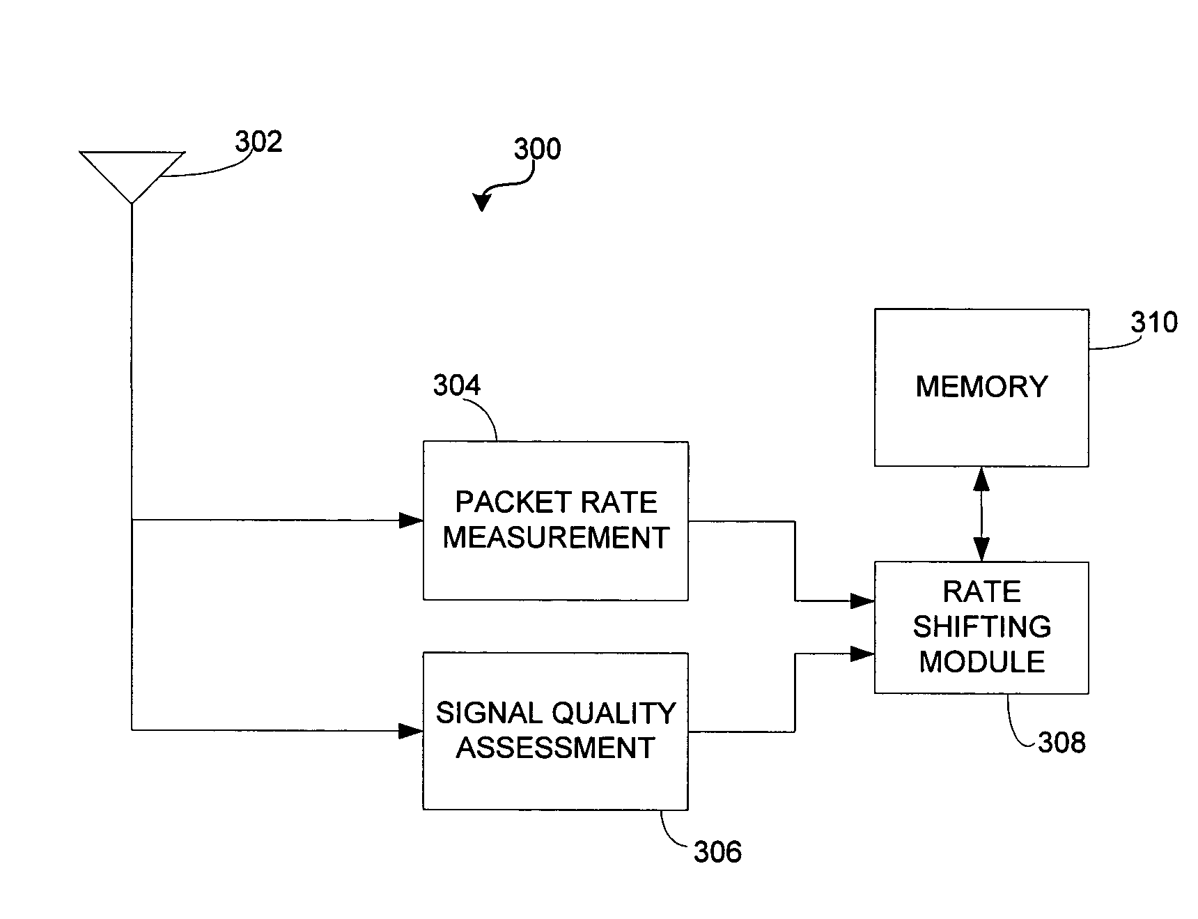
[0017] Throughout this description, the preferred embodiment and examples shown should be considered as exemplars, rather than limitations, of the present invention. The present invention a rate shifting technique that determines the reason for packet loss. In accordance with an aspect of the present invention, the present invention can differentiate whether packet loss is caused by poor signal quality or by packet collisions.

[0018] In accordance with an aspect of the present invention there is described herein a rate shifting algorithm employing at least one of signal strength, channel quality, packet loss rate and throughput to differentiate between packet loss due to packet collisions and packet loss due to poor signal quality.

[0019] In accordance with an aspect of the present invention, there is described herein a method for rate shifting. A transceiver can keep a history of the channel quality and the received signal strength of each successfully received packet and the numbe...


PUM


Abstract

A technique for determining when to change a data rate by determining the cause of packet loss. The technique distinguishes between collision mediated packet loss and poor signal mediated packet loss. Rate shifting to a lower rate is performed after determining poor signals are causing packet loss. After switching to a lower rate, the packet loss rate can be compared to the pre-switch packet loss rate. If the packet loss rate has not improved by shifting to a lower data rate, then the data rate can be shifted to a higher rate. The technique can use a combination of channel response, signal strength, packet loss rate and throughput to determine when to switch data rates. A communication unit can maintain separate histories for each unit it is communicating with and employ a different data rate for each unit.

Description

BACKGROUND OF THE INVENTION [0001] The present invention relates generally to communications and more particularly to methods for rate shifting to improve network performance and implementations of the aforesaid methods. [0002] Data rate shifting is a common mechanism to ensure a reliable wireless link. There are many ways that a wireless link can become degraded (e.g., noise, multipath, fading, interference, etc.). As the link is degraded it becomes increasingly difficult to operate the link at higher data rates because corrupted packets and the subsequent retries consume much of the available bandwidth. A reduction in the data rate is often effective in restoring the quality of the link since the lower data rates can accommodate greater corruptions to the link. [0003] Rate-shifting can be based on the number of packet retries. As the number of packet retries increases, or reaches a certain threshold, the data rate can be reduced. However, a problem with this technique is that pack...

Claims


Application Information

Patent Timeline
Patent Type & Authority Applications(United States)
IPC IPC(8): H04L12/28H04L12/56H04W24/00H04W28/22
CPCH04L43/0829H04L43/0888H04W28/22H04L47/25H04W24/00H04L47/14H04W28/0236H04W28/0242H04W8/04
Inventor QIAN, LULEWIS, MICHAEL E.
Owner CISCO TECH INC
Learn More