Burst optical communication apparatus

a technology of optical communication and burst signal, which is applied in the field of optical communication apparatus for transmitting burst signal, can solve the problems of inability to achieve signal transmission and inability to detect optical signals, and achieve the effect of preventing collision

Inactive Publication Date: 2005-11-10
PANASONIC CORP
View PDF7 Cites 37 Cited by
  • Summary
  • Abstract
  • Description
  • Claims
  • Application Information

AI Technical Summary

Benefits of technology

[0016] Therefore, an object of the present invention is to provide a large-capacity burst optical communication apparatus which is capable of preventing a collision among lights that are outputted from a plurality of optical transmitting circuits.

Problems solved by technology

However, such a conventional optical communication apparatus is provided only with a single optical transmitting circuit.
Therefore, if a plurality of such optical transmitting circuits are provided and are simultaneously output optical signals to a single optical receiving circuit, a collision occurs among these optical signals, and therefore, these optical signals cannot be respectively detected.
As a result, signal transmission cannot be achieved.

Method used


Image

  • Burst optical communication apparatus
  • Burst optical communication apparatus
  • Burst optical communication apparatus

Examples


first embodiment

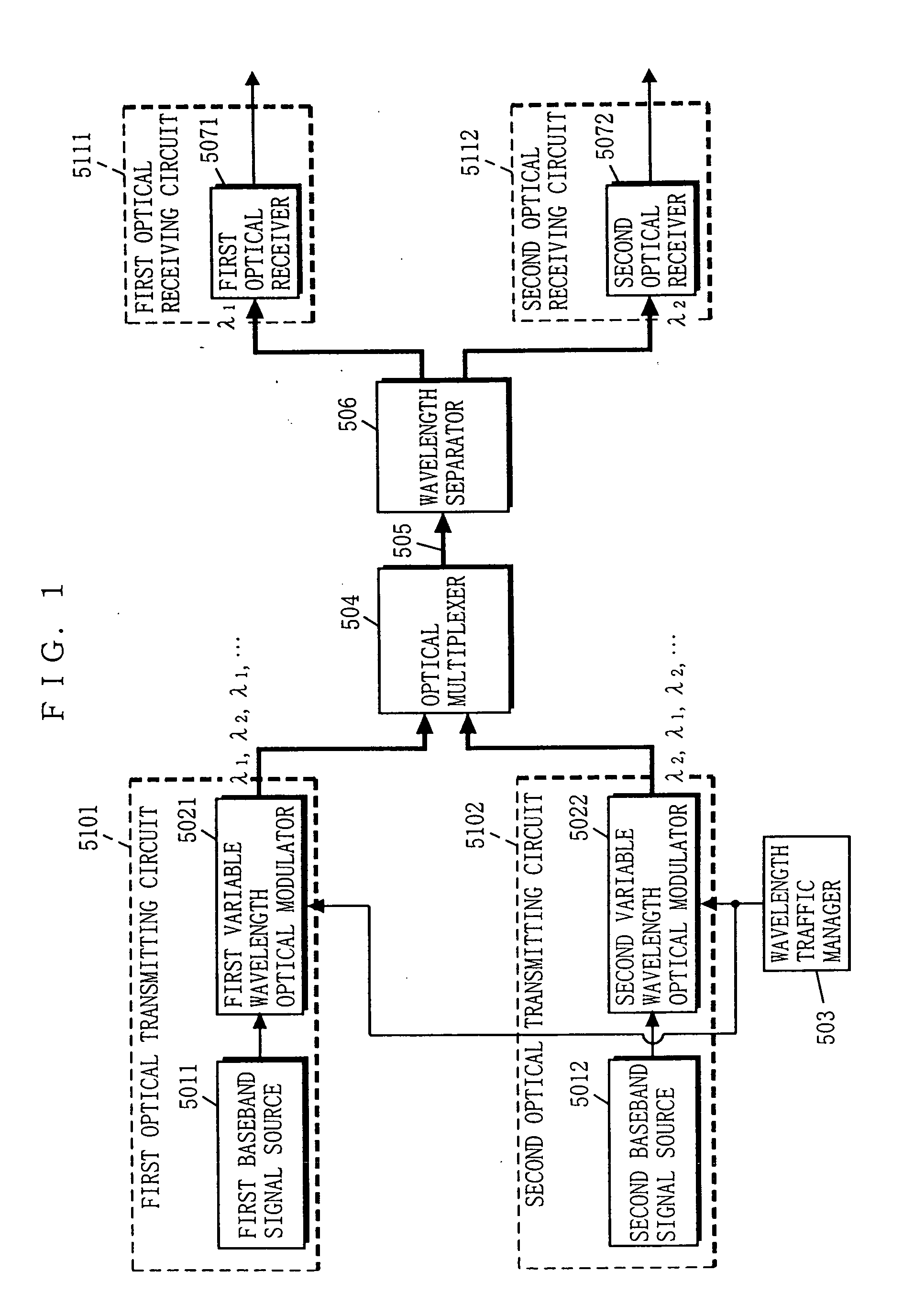
[0061]FIG. 1 is a block diagram showing the structure of an optical communication apparatus according to a first embodiment of the present invention. In FIG. 1, the optical communication apparatus includes first and second optical transmitting circuits 5101 and 5102, and the first and second optical receiving circuits 5111 and 5112. Such a structure allows the optical communication apparatus to achieve bidirectional burst (intermittent) transmission between the first and second optical transmitting circuits 5101 and 5102 and the first and second optical receiving circuits 5111 and 5112. Note that, in FIG. 1, components that are identical in structure to those described with reference to FIG. 8 are provided with the same reference numerals.

[0062] The optical communication apparatus of the first embodiment further includes a wavelength traffic manager 503 for managing the wavelengths of optical signals respectively outputted from first and second variable wavelength optical modulator...

second embodiment

[0070] An optical communication apparatus according to a second embodiment of the present invention is the one that solves problems of the optical communication apparatus according to the first embodiment, which are now described first.

[0071] The optical communication apparatus according to the first embodiment uses a baseband digital signal as the transmission signal. Therefore, if optical signals from a plurality of optical transmitting circuits are simultaneously provided to a single optical receiving circuit, a collision occurs among the transmission signals, and therefore, these optical signals cannot be detected. To solve this problem, as stated above, the burst optical signals outputted from the optical transmitting circuits are managed so as not to be simultaneously identical in wavelength, that is, to always differ in wavelength from each other. However, this management makes the system structure complicated. Moreover, if the optical transmitting circuits are placed apart ...

third embodiment

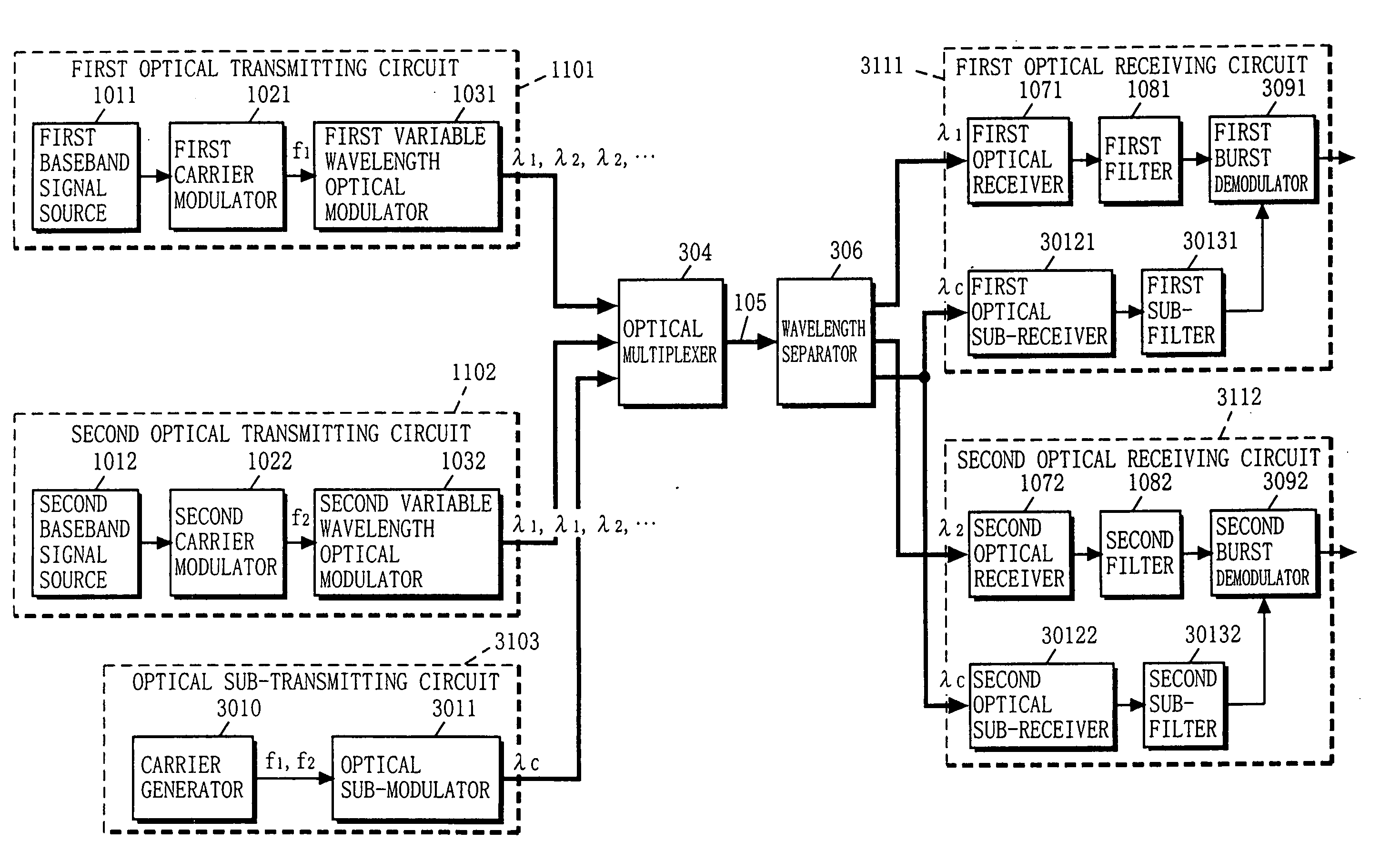
[0102] With reference to FIG. 4, the structure of an optical communication apparatus according to a third embodiment of the present invention will now be described. In FIG. 4, the optical communication apparatus of the third embodiment includes the first and second optical transmitting circuits 1101 and 1102, an optical sub-transmitter circuit 3103, and first and second optical receiving circuits 3111 and 3112. Note that, in FIG. 4, components that are identical in structure to those described with reference to FIG. 2 are provided with the same reference numerals.

[0103] The optical communication apparatus of the third embodiment further includes an optical multiplexer 304 for multiplexing lights outputted from the first and second optical transmitting circuits 1101 and 1102 and the optical sub-transmitter circuit 3103, the optical transmission line 105 for transmitting the multiplexed light, and a wavelength separator 306 for separating the light from the optical transmission line ...


PUM


Abstract

First and second carrier modulators each modulate a carrier having a different frequency from each other with a baseband input signal. First and second variable wavelength optical modulators each convert the modulated signal into an optical signal having a first or second wavelength. An optical multiplexer multiplexes the optical signals, and sends a multiplexed signal to an optical transmission line. A wavelength separator individually outputs wavelength components of the multiplexed signal. First and second optical receivers each convert these wavelength components into an electrical signal. First and second filters each pass only the signal components of each different frequency. First and second burst demodulators each demodulate the modulated signal. With such a structure, a large-capacity optical communication apparatus which is capable of simultaneously using the same wavelength without requiring wavelength management in optical transmitting circuits can be achieved at a low cost.

Description

[0001] This application is a divisional of U.S. application Ser. No. 09 / 695,883, filed Oct. 26, 2000.BACKGROUND OF THE INVENTION [0002] 1. Field of the Invention [0003] The present invention relates to optical communication apparatuses for transmitting a burst signal, and more specifically, to an optical communication apparatus for transmitting a burst signal by selectively switching signal paths by using a wavelength of the burst optical signal as address information. [0004] 2. Description of the Background Art [0005] In one conventional art, a variable wavelength light source is provided as a light source to an optical communication circuit. This variable wavelength light source sends a burst-like optical signal by using the wavelength thereof as address information. Further, a wavelength separator having output terminals each corresponding to a different wavelength is provided on an optical transmission line. With this structure, a high-speed, large-capacity burst optical communi...

Claims


Application Information

Patent Timeline
Patent Type & Authority Applications(United States)
IPC IPC(8): H04B10/00H04B10/04H04B10/155H04J14/02
CPCH04J14/02H04B10/505
Inventor FUSE, MASARU
Owner PANASONIC CORP
Why Eureka
Try Eureka