Insulated pitched roof system and method of installing same

a pitched roof and insulation technology, applied in the field of pitched roof systems and methods, can solve the problems of affecting the fixing effect of nails, and unable to drive holes through the roof substrate and wood deck

Inactive Publication Date: 2005-11-17
POLYOAM PROD
View PDF35 Cites 21 Cited by
  • Summary
  • Abstract
  • Description
  • Claims
  • Application Information

AI Technical Summary

Benefits of technology

[0014] One embodiment of the present invention includes an insulated pitched roof system and method of installation for a sloped or pitched roof deck of wood, metal, concrete or other material. The pitched roof system according to an embodiment of the present invention is energy efficient and is particularly suited to a roof having a 2:12 pitch or greater.
[0017] The method of installing the pitched roof system according to an embodiment of the present invention is a simple operation, non-labor intensive, economical and does not require excessive installation time. The pitched roof system will withstand the long-term effects of temperature variations and climatic conditions experienced by the pitched roof system under normal circumstances.

Problems solved by technology

In either case, it is undesirable to drive numerous holes through the roof substrate and wood deck since these nail holes provide a potential leak path in the pitched roof system.
High wind loading conditions also affect the roof components secured with nails.
In areas near salt water the effectiveness of nails is diminished over time due to corrosion of the nails.
Additionally, nails get loose over a period of time.
Some decks, such as concrete or steel decks, cannot be nailed into.
Non-nailable decks (concrete, steel, etc.) use a wire tie or other cumbersome and expensive system to fasten the roof components to the pitched roof deck.
Using mortar is a slow procedure and labor intensive as the mortar must first be prepared, typically at ground level, in buckets which must then be raised to the pitched roof deck, and then the mortar is applied to the roof substrate.
The mortar adds unnecessary weight to the roof system.
Furthermore, the strength of the completed bond between the tile roof component and the roof substrate can be unsatisfactory.
During high wind loading conditions, such as that experienced during a hurricane or a tornado, the tile roof components frequently release from the roof structure and become life threatening, flying projectiles.
The flying tile roof components result in additional danger during these devastating events and further increase the tremendous burden of clean up after these catastrophic events.

Method used


Image

  • Insulated pitched roof system and method of installing same
  • Insulated pitched roof system and method of installing same
  • Insulated pitched roof system and method of installing same

Examples


Embodiment Construction

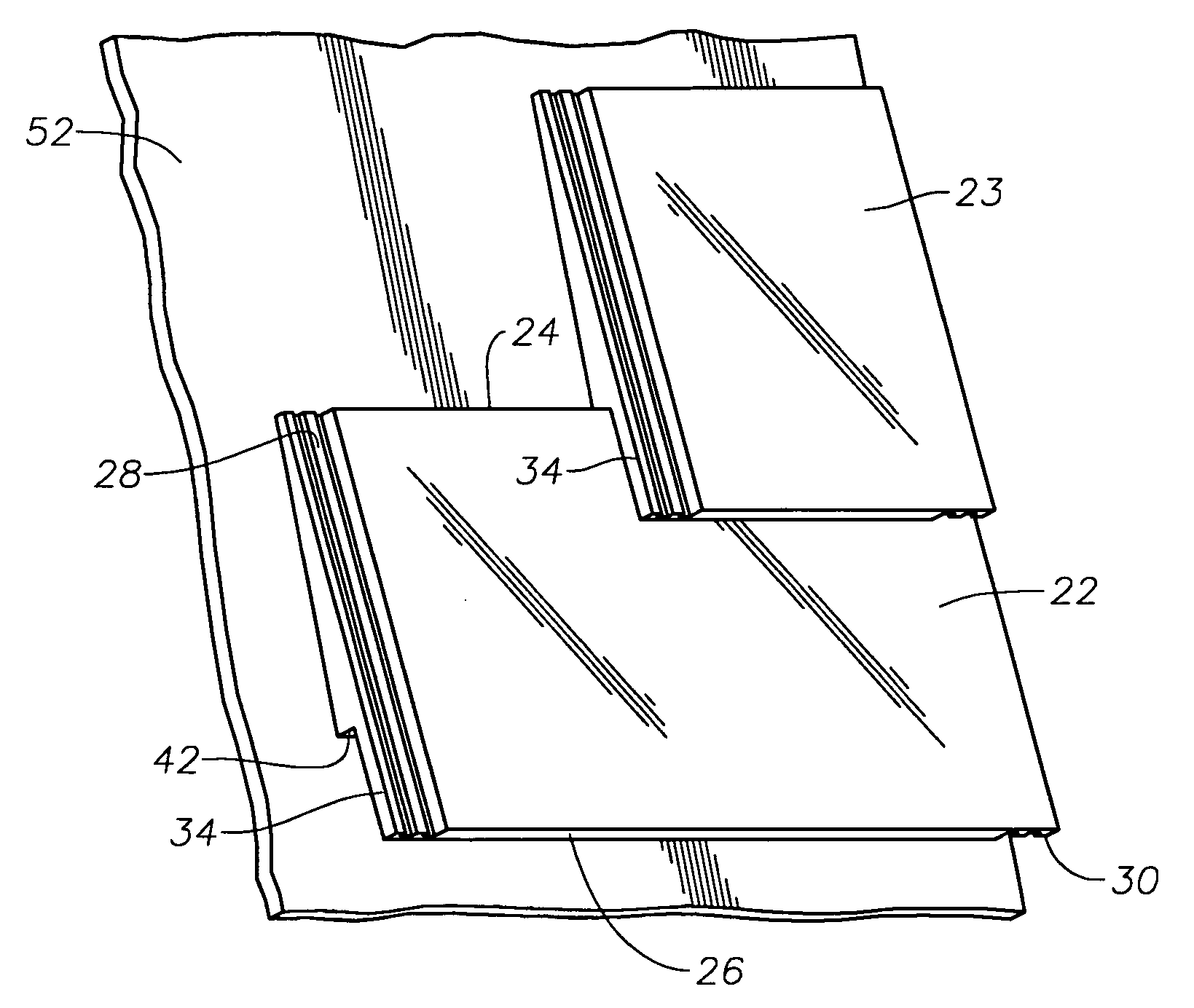
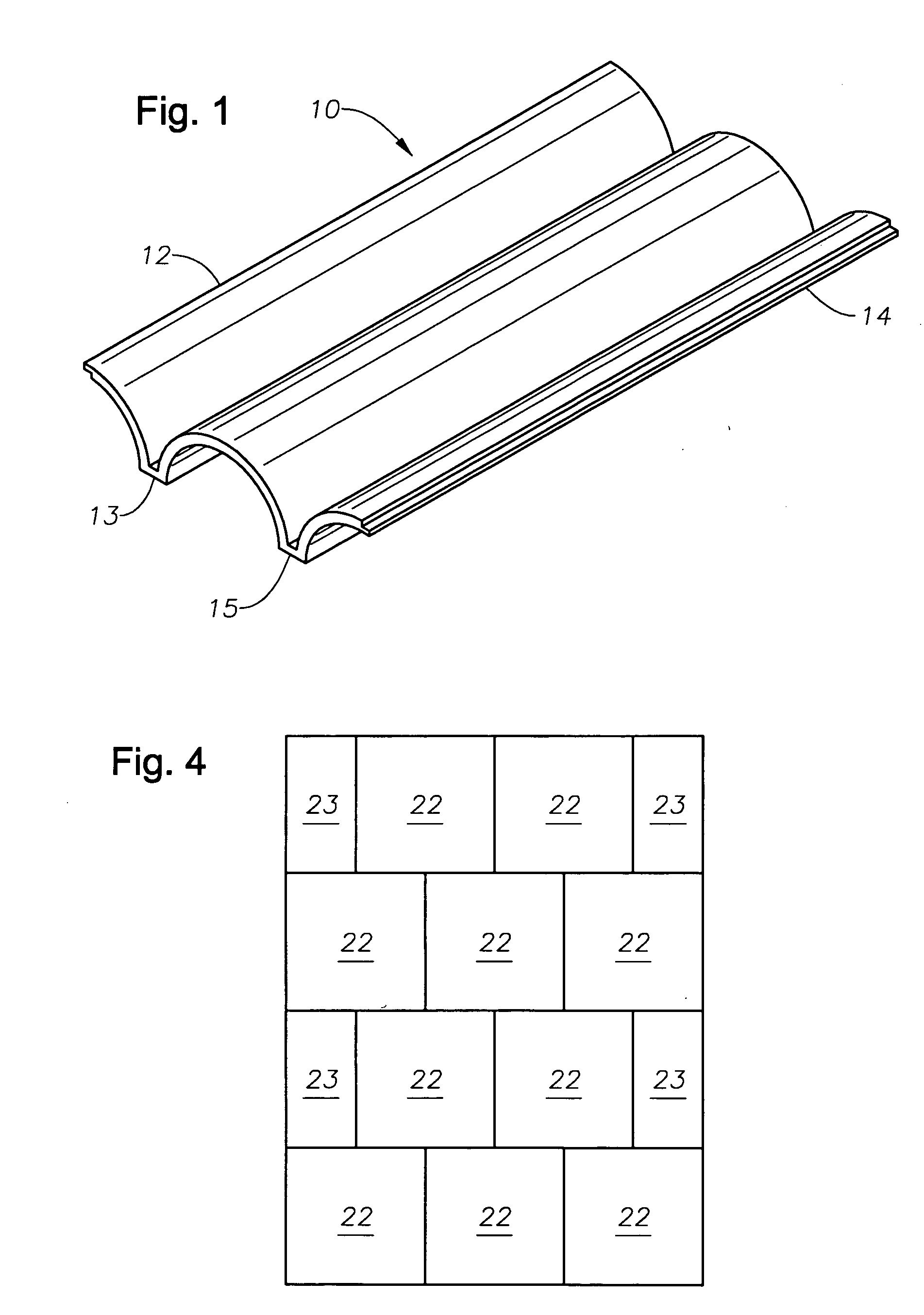
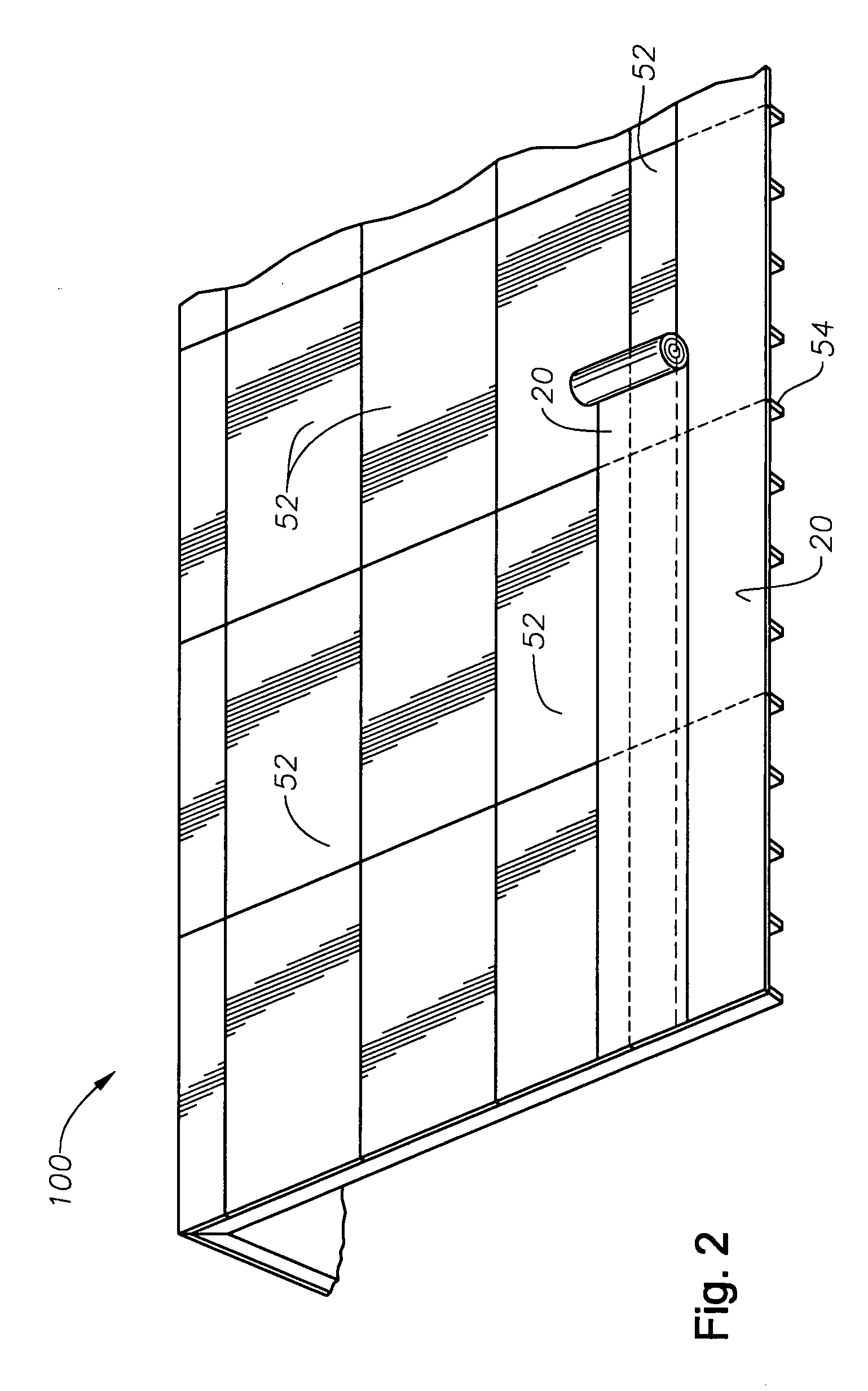
[0029] The insulated pitched roof system and method of installing same, generally designated as 100, will now be described in greater detail with specific reference to the drawings. Referring to FIG. 1, the pitched roof system 100 includes a roof component, designated generally as 10. The roof component 10 shown in perspective view in FIG. 1 is known as a semi-circular roof tile. It is to be understood that the system and method of the present invention 100 is not limited to semi-circular roof tiles. Rather, the system and method 100 can include roof components 10 of other types and configurations. For example, flat roof tiles and reverse curve roof tiles are just a few of the other types that can be used with the system and method 100. Typically, the tile components 10 are made from cementitious or clay materials. It is also to be understood that the system and method of the present invention 100 is not limited to clay or cementitious roof tiles 10 but is also applicable to roof co...


PUM


Abstract

The present invention is an insulated pitched roof system for a sloped deck in which an insulating component is adhered to the sloped deck and the roof tiles are adhered to the insulating component with an adhesive, preferably a polymer adhesive. The insulating component includes a board or sheet material which is adhered to the roof deck. The insulating component is preferably adhered directly to the roof deck with a polymer adhesive. The insulating component preferably includes interlocking sides for forming a water tight connection between adjacently joined insulating components. Additionally, the insulating components include an end lap portion to form an overlapping portion between adjacent rows of insulating components. In a preferred embodiment, the overlapping portion is adhered together to form a unitary insulative and waterproof layer.

Description

CROSS-REFERENCE TO RELATED APPLICATIONS [0001] Applicants have pending related U.S. application Ser. No. 10 / 294,959, published May 15, 2003. Applicants hereby incorporate by reference U.S. patent application Ser. No. 10 / 294,959 in its entirety.STATEMENTS REGARDING FEDERALLY SPONSORED RESEARCH OR DEVELOPMENT [0002] Not Applicable. REFERENCE TO A MICROFICHE APPENDIX [0003] Not Applicable. BACKGROUND OF THE INVENTION [0004] 1. Field of the Invention [0005] The present invention relates to a pitched roof system and method, and particularly to a system and method for insulating the pitched roof and attaching the roofing components. [0006] 2. Description of the Related Art [0007] There are two basic types of roofs: flat and pitched. Pitched roofs come in a few basic styles, all of which are relevant to the present invention. A duo-pitched roof has two sloping sides joined along the top with end vertical walls called a gable end. This is probably the most common form of pitched roof. If th...

Claims


Application Information

Patent Timeline
Patent Type & Authority Applications(United States)
IPC IPC(8): E04B5/00E04D1/34E04D13/16
CPCE04D1/34Y02B30/94E04D2001/3435E04D13/1618Y02A30/00Y02B30/90E04D1/2916
Inventor FAULKNER, DAVID H.FERRANTE, ROBERT L.HUBER, E. RICHARDMURRAY, PAT L.
Owner POLYOAM PROD
Why Eureka
Try Eureka