Wind-powered linear motion hydrogen production systems

a technology of linear motion and hydrogen production system, which is applied in the direction of propulsive elements, electrical equipment, towing/pushing equipment, etc., can solve the problems of spilled hydrogen merely dispersing, environmental risks, and current reliance on fossil fuels, and achieve the effect of efficient harnessing wind power and producing hydrogen

Inactive Publication Date: 2005-11-17
MELLER MOSHE
View PDF20 Cites 50 Cited by
  • Summary
  • Abstract
  • Description
  • Claims
  • Application Information

AI Technical Summary

Benefits of technology

[0011] It is an object of the invention to provide a system for efficiently harnessing wind power to produce hydrogen.

Problems solved by technology

The world's current reliance on fossil fuels poses many problems.
In addition, fossil fuel use poses environmental risks in drilling to retrieve the fuel, transporting the fuel to consumers, and through the by-products of fossil fuel consumption.
Because hydrogen dissipates when leaked, a major hydrogen spill would amount to little more than a waste of valuable fuel.
Thus, in contrast to the ecological disasters caused by oil spills, spilled hydrogen merely dissipates.
In addition, increased use of hydrogen-powered fuel cells will reduce world dependence on conventional fuels, which are subject to volatility in price and supply.
However, this method of hydrogen extraction adds considerable weight and complexity to cars, and yet still produces some tail-pipe emissions.
Therefore, this approach has largely been abandoned.
However, both types of wind parks suffer several disadvantages.
In addition, in order to produce energy from wind cost-effectively, the windmills must have very large blade spans.
Therefore, the main shaft of the windmill rotates slowly, and efficiency at the central area of the windmill is low.
However, power generators require a relatively high rate of rotation to function efficiently.
However, offshore wind parks are currently limited to shallow water, thereby restricting possible locations.

Method used


Image

  • Wind-powered linear motion hydrogen production systems
  • Wind-powered linear motion hydrogen production systems
  • Wind-powered linear motion hydrogen production systems

Examples


Embodiment Construction

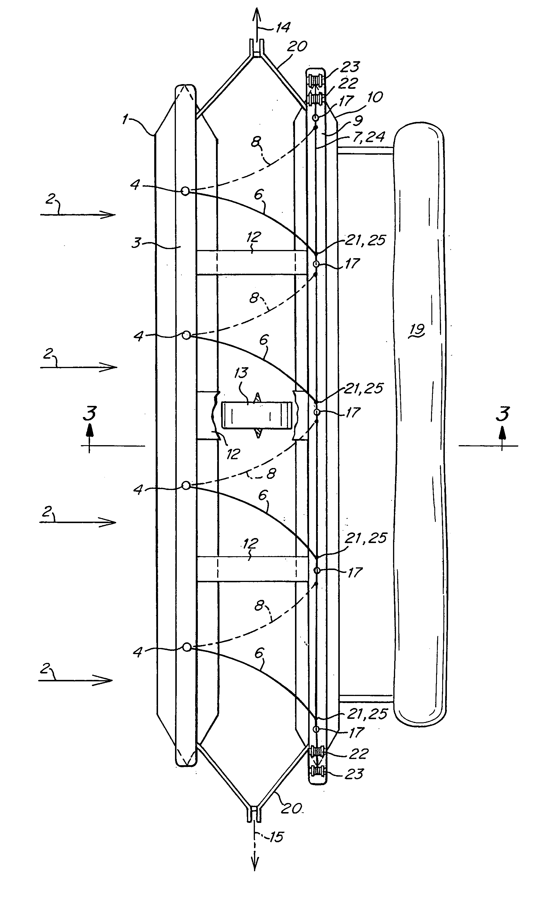
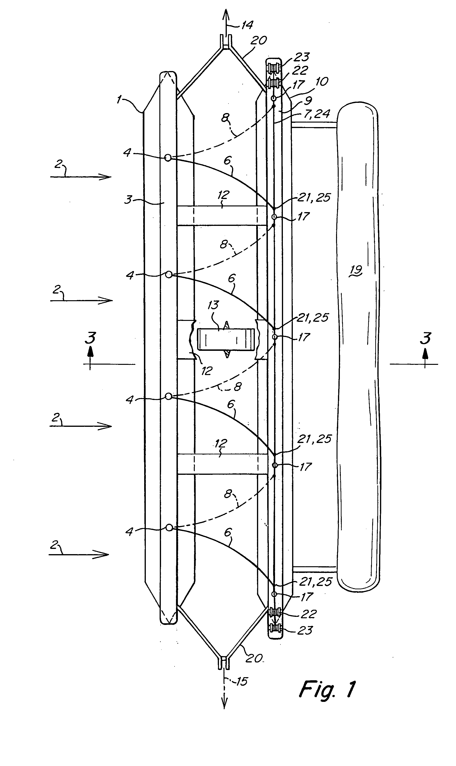
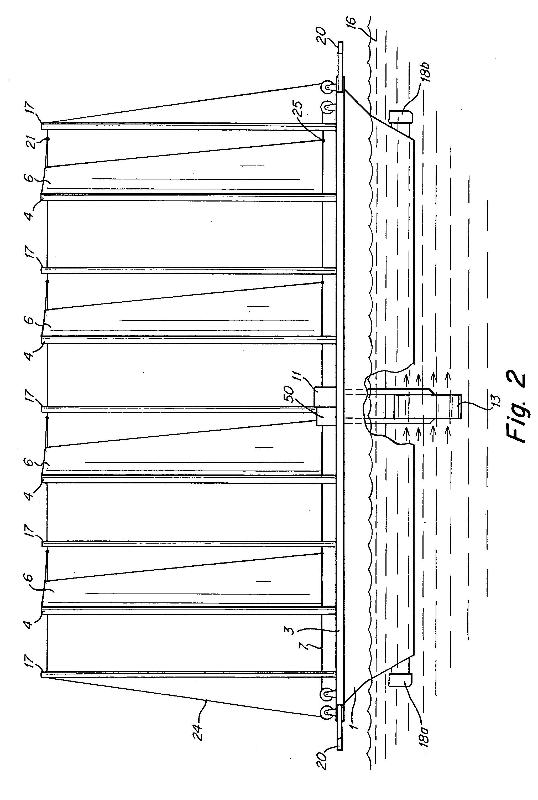
[0027]FIGS. 1-6 show a system for generating hydrogen according to a first embodiment of the present invention. Primary floating element 1 and secondary floating element 10, which are, for example, pontoons or the like, are connected by connectors 12 and support the vessel so as to allow it to float in a body of water 16. A plurality of sails 6 are mounted on the vessel via poles 4, which are supported by supporting element 3 mounted on the primary floating element 1. The sails 6 may, for example, be made from either flexible or rigid sail materials, and the poles may, for example, be constructed as rigid poles as vertical cables. Wind blowing in direction 2 is caught by the sails 6 to drive the vessel in direction 14. The direction of the vessel may be controlled via rudder 18b (See FIG. 2). The vessel moves in direction 14 along a path that is substantially linear and substantially perpendicular to the wind direction 2. The motion of the vessel relative to the water creates a flow...


PUM

PropertyMeasurementUnit
heightaaaaaaaaaa
heightaaaaaaaaaa
areaaaaaaaaaaa

Abstract

A system for generating hydrogen is provided which includes at least one vessel which floats in water. At least one sail for capturing wind to move the vessel reciprocally along a substantially linear path is mounted on the vessel. A power generation system is provided for converting movement of the vessel relative to the water into electricity. And an onboard hydrogen production system produces hydrogen by electrolysis using the electricity generated by the power generation system.

Description

CROSS-REFERENCE TO RELATED APPLICATIONS [0001] This application claims the benefit under 35 U.S.C. §119(e) of U.S. provisional patent applications Ser. No. 60 / 572,259 filed May 17, 2004, Ser. No. 60 / 575,304 filed May 28, 2004 and Ser. No. 60 / 576,190 filed Jun. 1, 2004.FIELD OF THE INVENTION [0002] The present invention relates to a system of producing hydrogen by converting wind power into electricity for use in producing hydrogen via sail-driven vessels. BACKGROUND OF THE INVENTION [0003] The world's current reliance on fossil fuels poses many problems. Fossil fuels are currently consumed 100,000 times faster than they are made, sparking speculation as to how much longer the world's fossil fuel supplies will last. In addition, fossil fuel use poses environmental risks in drilling to retrieve the fuel, transporting the fuel to consumers, and through the by-products of fossil fuel consumption. Still further, two thirds of the world's oil is concentrated in the Middle East, in the con...

Claims


Application Information

Patent Timeline
Patent Type & Authority Applications(United States)
IPC IPC(8): C25D17/00F03B13/00F03B17/06F03D9/00H01M8/04
CPCB63B35/44B63B2035/4466B63H9/04F03B13/00F03B17/061Y02E10/72F03D9/008F05B2220/61Y02E10/28Y02E70/10F03B17/062F03D9/32Y02E10/20Y02E10/728Y02E60/36Y02P70/50
Inventor MELLER, MOSHE
Owner MELLER MOSHE
Why Eureka
Try Eureka