
Horizontal shock suspension system

Inactive Publication Date: 2005-11-17
RIZE INDS
View PDF6 Cites 2 Cited by
  • Summary
  • Abstract
  • Description
  • Claims
  • Application Information

AI Technical Summary

Benefits of technology

[0005] The devices and methods described below provide for installation of horizontally mounted shock absorbers for cars and trucks. The horizontally mounted suspension system provides for greater damping efficiency in the small area of the wheel well. Additionally, the use of full travel shocks in an area where they were previously not able to be used results in less bottoming out of the shocks.
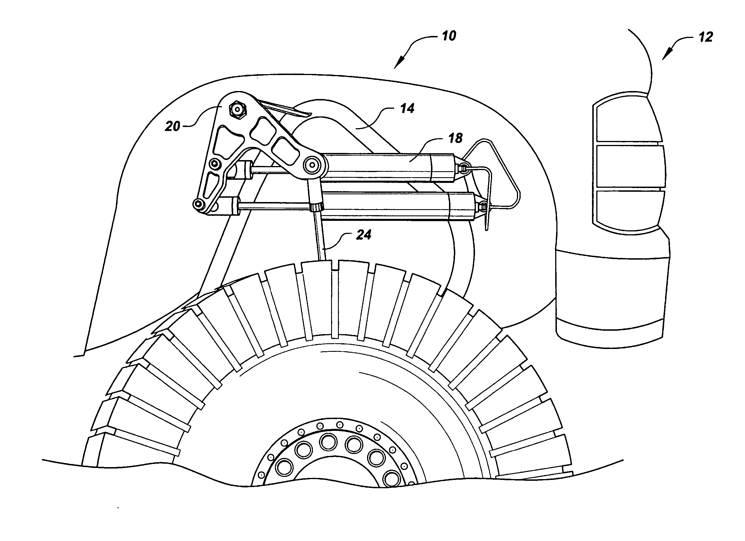
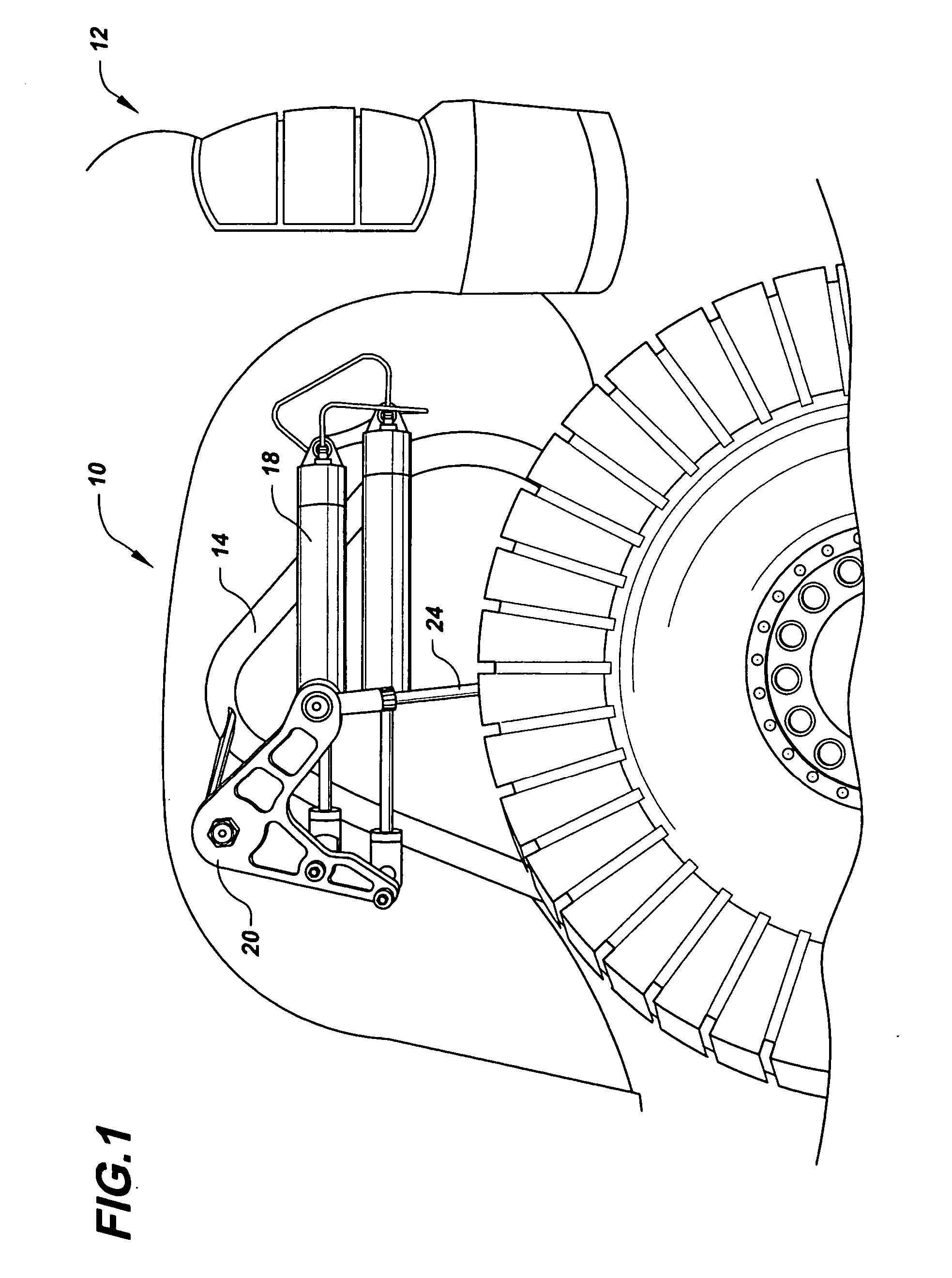
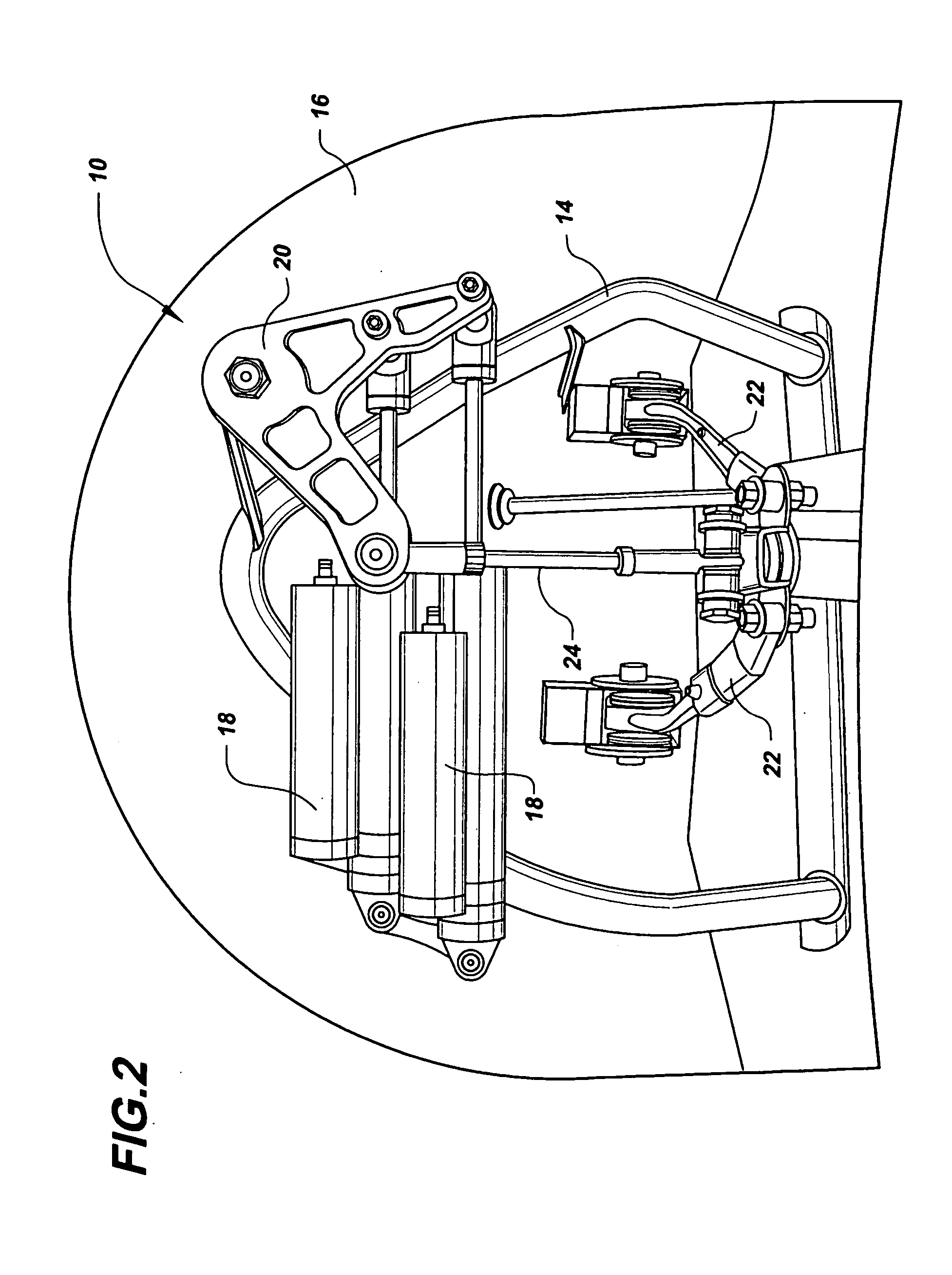
[0008] Linkage, pivot points, and the shock absorber are key in preserving a smooth ride within the truck. Vehicle springs maintain ride height, effect body motion (such as pitch and roll) and they affect ride quality and adhesion. The pivot arm is contained for control of the suspension when the truck is operated. The pivot arm is positioned to project transversely from the suspension and is adapted to be attached to the shock and the shock transfer rod. The shock transfer rod functions to transmit movement of the wheel to the suspension. The shock is positioned transversely with respect to the shock transfer rod. This configuration results in a horizontally mounted suspension system. The system is especially well suited for use with off road trucks, and for use with lift kits, where additional absorption is desirable.

Problems solved by technology

With the vertical shock suspension systems, the size of the shock absorbers is limited by the available space in the wheel well.
This results in limited travel of the entire shock as well as limited damping.
Alternatively, shorter shocks may be used, however, this results in less ability to prevent bouncing of the vehicle.
However, the use of shorter springs results in reduced travel and stiffer spring thus resulting in some loss of ride quality.
Too much lowering causes a very harsh ride, poor handling, and possible suspension damage.
However, the vertical orientation of shock absorbers in some configurations limits travel of the shock absorbers.

Method used


Image

  • Horizontal shock suspension system
  • Horizontal shock suspension system
  • Horizontal shock suspension system

Examples


Embodiment Construction

[0011]FIGS. 1 and 2 illustrate a horizontal shock suspension system 10 installed on a truck 12. The suspension system 10 comprises a shock hoop 14 that is fixedly attached to the frame 16 of a truck or automobile, two shock absorbers 18, a pivot arm 20, and upper control arm 22, and a shock transfer rod 24.

[0012] The shock hoop 14 comprises a generally “U” shape tube or rod with fitting on either end adapted to be fixed to the frame or subframe of the truck. The shock hoop serves primarily as a means for securing shock absorbers to the frame in place of the original equipment shock absorber mounts fixed to the frame above the wheel well. The shock hoop extends from a convenient point on the frame, in this case it extends upwardly from a point below the upper end of the vertically oriented shock absorbers with which it is typically used, and also below the horizontally oriented shock absorbers 18. The shock hoop is modified with the provision of a mounting bracket adapted for mounti...


PUM


Abstract

A horizontally mounted vehicle suspension system is provided. The suspension system contains at least one horizontally mounted shock, which provides for a more comfortable ride within the vehicle. The configuration increases the space to accommodate for the shock or shock strut, as well as allows for the use of full travel shocks in small spaces. The full shock length, with all associated benefits can be used within a smaller space. The suspension system may be used with traditional shock absorbers or shock struts.

Description

FIELD OF THE INVENTIONS [0001] The inventions described below relate the field of auxiliary frame systems for a vehicle wheel suspension system. BACKGROUND OF THE INVENTION [0002] Conventional suspension systems for cars and trucks comprise shock absorbers or shock struts that are mounted vertically within the suspension system. The vertically mounted shock absorbers fits easily into the wheel well. [0003] With the vertical shock suspension systems, the size of the shock absorbers is limited by the available space in the wheel well. This results in limited travel of the entire shock as well as limited damping. Where a small area is defined, the lowering or raising of the vertical shock mounts has been a solution. Alternatively, shorter shocks may be used, however, this results in less ability to prevent bouncing of the vehicle. A common way to lower a vehicle for improved handling or appearance is to install shorter springs and shocks. However, the use of shorter springs results in ...

Claims


Application Information

Patent Timeline
IPC IPC(8): B60G1/00B60G13/00
CPCB60G13/005B60G2200/144B60G2202/21B60G2204/422B60G2204/13B60G2204/421B60G2202/24
Inventor RILEY, JOSEPH K.SPINALI, GIOVANNI G.
Owner RIZE INDS
Learn More