
Suspension bushing and suspension device

a suspension device and bushing technology, applied in the direction of springs/dampers, mechanical devices, transportation and packaging, etc., can solve the problems of reduced vehicle maneuvering stability, deformation of rubber between the inner cylinder and the outer cylinder, and worsening of vibration characteristics, so as to improve maneuvering stability without adversely affecting ride quality

Inactive Publication Date: 2021-10-07
HONDA MOTOR CO LTD
View PDF0 Cites 1 Cited by
  • Summary
  • Abstract
  • Description
  • Claims
  • Application Information

AI Technical Summary

Benefits of technology

The present invention aims to improve the maneuvering stability of a suspension bushing without compromising the ride quality. By reducing misalignment between the inner and outer cylinders, the invention reduces rubber deformation when the suspension bushing receives an external force. This deformation can lead to reduced vehicle maneuvering stability. The invention achieves this through a reduction in rubber volume or by using rubber with high hardness. The invention also addresses the possibility of worsening vibration characteristics and adversely affecting ride quality through increased rubber rigidity. Overall, the invention provides a suspension bushing and suspension device that improves maneuvering stability while maintaining ride quality.

Problems solved by technology

However, the rubber between the inner cylinder and the outer cylinder deforms when the suspension bushing receives an external force.
If this deformation of the rubber is significant, the vehicle maneuvering stability is reduced.
However, when the rigidity of the rubber is increased, there is a possibility that the vibration characteristics are worsened and the ride quality is adversely affected.

Method used


Image

  • Suspension bushing and suspension device
  • Suspension bushing and suspension device
  • Suspension bushing and suspension device

Examples


Embodiment Construction

[0033]Preferred embodiments of a suspension bushing and a suspension device according to the present invention will be presented and described below with reference to the accompanying drawings.

1. Configuration of Suspension Device 10

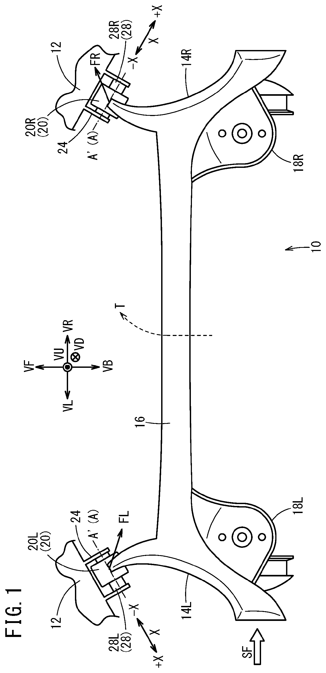
[0034]A suspension device 10 according to the present embodiment will be described using FIG. 1. In FIG. 1, VF (upward in the plane of the drawing) indicates the forward direction of a vehicle body 12 and VB (downward in the plane of the drawing) indicates the backward direction of the vehicle body 12. Furthermore, VR (rightward in the plane of the drawing) indicates the rightward direction of the vehicle body 12 and VL (leftward in the plane of the drawing) indicates the leftward direction of the vehicle body 12. Yet further, VU (toward the viewer from the plane of the drawing) indicates the upward direction of the vehicle body 12 and VD (away from the viewer from the plane of the drawing) indicates the downward direction of the vehicle body 12.

[0035]Th...


PUM


Abstract

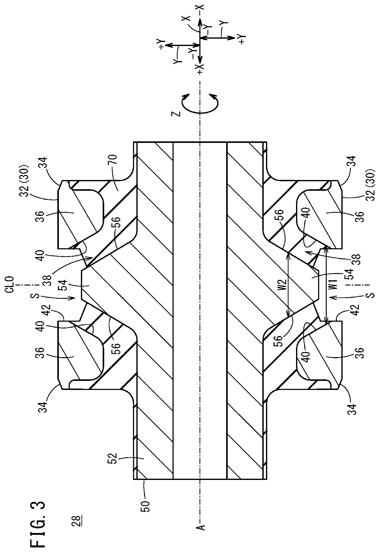
Provided are a suspension bushing and a suspension device with which maneuvering stability can be improved without adversely affecting ride quality. Protrusions are formed on the outer circumferential surface of an inner tube, and slits are formed on the inner circumferential surface of an outer tube. The protrusions are arranged in the slits and have a tapered shape in which their width in a direction parallel to an axial line decreases as the distance from the axial line increases. The slits have a shape such that a gap in the direction parallel to the axial line decreases as the distance from the axial line increases.

Description

TECHNICAL FIELD[0001]The present invention relates to a suspension bushing attached between a vehicle body and a suspension arm, and to a suspension device of torsion-beam type that uses this suspension bushing.BACKGROUND ART[0002]Japanese Laid-Open Patent Publication No. 2010-054017 discloses an antivibration apparatus (antivibration bushing) used as a suspension bushing of an automobile. This antivibration bushing includes a space filled with rubber between an inner cylinder and an outer cylinder, and a protrusion on the outer circumference of the inner cylinder. When an external force in a direction orthogonal to the axis is applied to the antivibration bushing, the inner cylinder moves in the axis-orthogonal direction and the protrusion contacts the outer cylinder. In this way, the rigidity against the external force in the axis-orthogonal direction is increased.SUMMARY OF INVENTION[0003]It is important to reduce the misalignment between the center of the outer cylinder and the ...

Claims


Application Information

Patent Timeline
IPC IPC(8): B60G21/05F16F1/38B60G7/02
CPCB60G21/052F16F1/38B60G7/02B60G2204/4104B60G2200/21B60G2206/20B60G2202/14F16F1/387B60G2200/20B60G21/051B60G2204/1434B60G2204/41B60G2204/4106F16F1/3863
Inventor NISHIMURA, TETSUJI
Owner HONDA MOTOR CO LTD
Learn More