Rotational angle sensing device and assembling method thereof

a sensing device and rotational angle technology, applied in galvano-magnetic devices, galvano-magnetic hall-effect devices, instruments, etc., can solve the problems of substantial difference, inability to provide the accommodating space for the first and second hall ics b>3, and difficulty in measuring rotational angle, so as to improve the arrangement of two magnetic sensing elements

Active Publication Date: 2005-11-17
DENSO CORP
View PDF4 Cites 74 Cited by
  • Summary
  • Abstract
  • Description
  • Claims
  • Application Information

AI Technical Summary

Benefits of technology

[0009] The present invention addresses the above disadvantage. Thus, it is an objective of the present invention to provide a rotational angle sensing device, which has improved arrangement of two magnetic sensing elements and measures a rotational angle in a range of 0 to 360 degrees. It is a further objective of the present invention to provide a method for assembling such a rotational angle sensing device.

Problems solved by technology

Therefore, in a case where the available accommodating space is relatively small, it is difficult to provide the accommodating spaces for accommodating the first and second Hall ICs 3, 4.
Thus, in such a case, when the prior art rotational angle sensing device is used, the first Hall IC 3 and the second Hall IC 4 cannot be spaced from one another, and therefore the rotational angle cannot be measured.
Furthermore, in the prior art rotational angle sensing device, since the first Hall IC 3 and the second Hall IC 4 are spaced from one another, a difference in the environmental condition (e.g., temperature) may exist between the first Hall IC 3 and the second Hall IC 4 to cause a substantial difference in the output between the first Hall IC 3 and the second Hall IC 4, resulting in deterioration of the accuracy of the measured angle.

Method used


Image

  • Rotational angle sensing device and assembling method thereof
  • Rotational angle sensing device and assembling method thereof
  • Rotational angle sensing device and assembling method thereof

Examples


first embodiment

[0029] A first embodiment of the present invention will be described with reference to FIGS. 1 to 6.

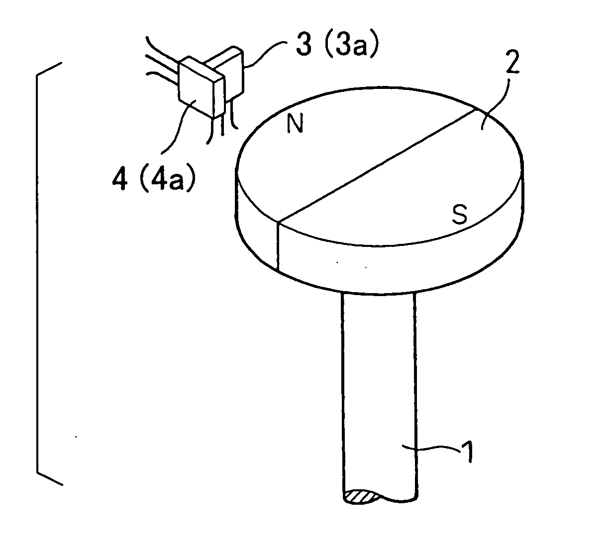
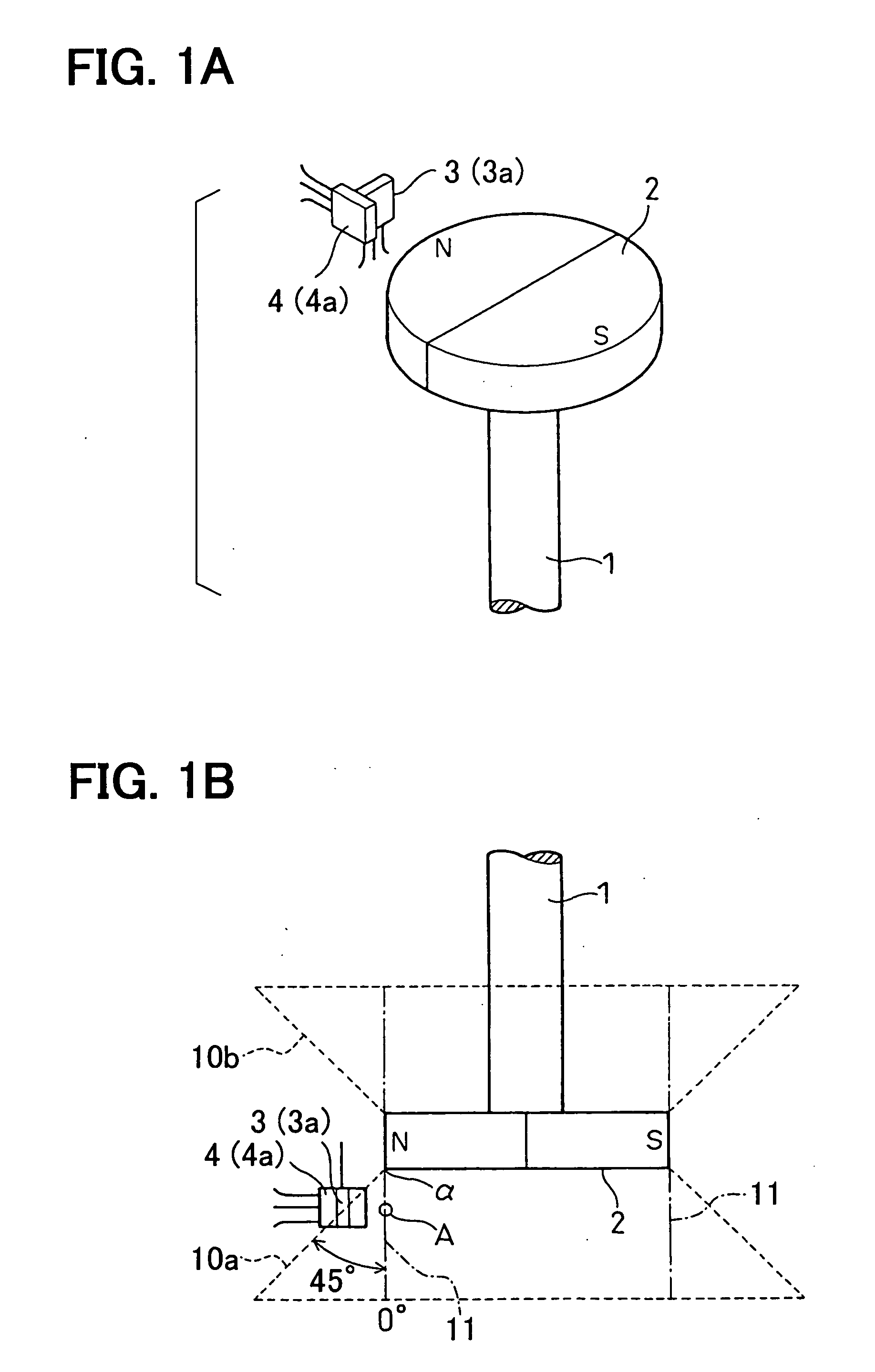
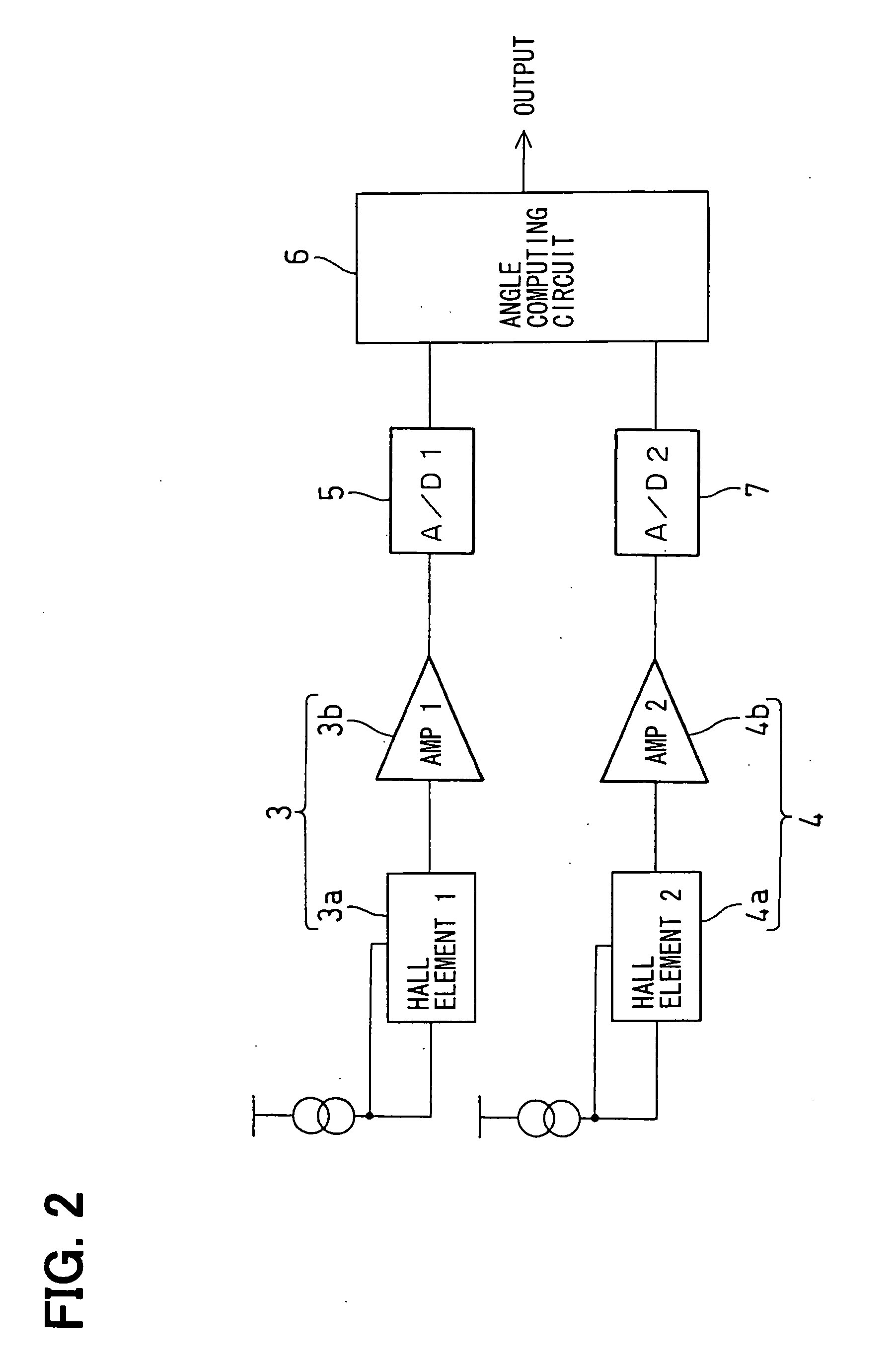
[0030] First, a basic structure of a rotational angle sensing device according to the first embodiment will be described with reference to FIGS. 1A to 2. FIG. 1A is a schematic perspective view of the rotational angle sensing device, and FIG. 1B is a schematic inverted side view of the rotational angle sensing device. FIG. 2 is a schematic circuit diagram of the rotational angle sensing device.

[0031] The rotational angle sensing device of the present embodiment measures a rotational angle of a rotatable shaft 1 of, for example, a throttle valve (e.g., a degree of opening of the throttle valve). The rotational angle sensing device includes a magnet 2 and first and second Hall ICs 3, 4. The magnet 2 is secured to thr rotatable shaft 1 (a rotatable member, which is one of two members that make relative rotation therebetween). The first and second Hall ICs 3, 4 are mounted to an undepic...

second embodiment

[0055] A second embodiment of the present invention will be described with reference to FIG. 7.

[0056] In the first embodiment, the first Hall IC 3, which includes the first Hall element 3a, is arranged adjacent the second Hall IC 4, which includes the second Hall element 4a.

[0057] In the second embodiment, the first Hall element 3a and the second Hall element 4a are arranged in a single chip 8. The first and second Hall elements 3a, 4a, which are encapsulated in the single chip 8, are arranged in a manner similar to that of the first embodiment. Thus, the magnetic sensing surface of the first Hall element 3a is parallel to the tangent line or the tangent plane, which is tangent to the outer peripheral circular edge of the magnet 2, and the magnetic sensing surface of the second Hall element 4a is perpendicular to the tangent line or the tangent plane, which is tangent to the outer peripheral circular edge of the magnet 2. Therefore, the magnetic sensing surface of the second Hall ...

third embodiment

[0060] A third embodiment according to the present invention will be described with reference to FIGS. 8A to 9.

[0061] In the first and second embodiments, there is described the case where the single magnet 2 is used.

[0062] In the third embodiment, as shown in FIG. 8, two substantially identical coaxial magnets (main and auxiliary magnets) 2, which generally have the same radial thickness, the same thickness and the same magnetic force, are provided. The magnets 2 are spaced from one another in the axial direction of the rotatable shaft 1. The first and second Hall elements 3a, 4a are positioned between the two magnets 2 in the axial direction. Here, the settings, such as the diameter of each magnet2, the gap between each magnet 2 and the first and second Hall elements 3a, 4a and the installation angle of the first and second Hall elements 3a, 4a relative to the outer peripheral edge a of each magnet 2, are the same as those of the first embodiment.

[0063] Next, the advantage of t...


PUM


Abstract

A magnet is provided to one of two members, which make relative rotation therebetween. First and second Hall elements are arranged adjacent to each other and are provided to the other one of the two members. A magnetic sensing surface of the first Hall element is generally perpendicular to a magnetic sensing surface of the second Hall element, and a relative rotational angle between the two members is determined through the first and second Hall elements based on a magnetic flux, which is generated by a magnetic flux generating portion of the magnet and passes through the first and second Hall elements toward a magnetic flux attracting portion of the magnet.

Description

CROSS REFERENCE TO RELATED APPLICATION [0001] This application is based on and incorporates herein by reference Japanese Patent Application No. 2004-145028 filed on May 14, 2004. BACKGROUND OF THE INVENTION [0002] 1. Field of the Invention [0003] The present invention relates to a rotational angle sensing device, which measures a relative rotational angle between two members (e.g., a rotatable member and a non-rotatable member) without making any physical contact. The present invention further relates to an assembling method of such a rotational angle sensing device. [0004] 2. Description of Related Art [0005]FIGS. 10A and 10B show a prior art rotational angle sensing device, which measures a wide range of rotational angles through use of a magnet and magnetic sensing elements (see for example, Japanese Unexamined Patent Publication No. 2003-75108). [0006] The rotational angle sensing device includes a circular disk shaped magnet 2 and first and second Hall ICs 3, 4. An outer periph...

Claims


Application Information

Patent Timeline
Patent Type & Authority Applications(United States)
IPC IPC(8): G01D5/245G01B7/14G01B7/30G01D5/14G01D5/244
CPCG01D5/24419G01D5/145
Inventor KAWASHIMA, TAKASHIHAMAOKA, TAKASHIBAN, TAKAO
Owner DENSO CORP
Why Eureka
Try Eureka