Damper for speaker device, speaker device using the damper and manufacturing method therefor

a technology for speaker devices and dampers, which is applied in the direction of deaf-aid sets, transducer details, electrical transducers, etc., can solve the problems of increasing the outer dimension of the speaker, the durability of the part to which the force is applied, and the damper becomes a problem, so as to prevent partial bending or cutting of the elastic part, the effect of rust resistan

Inactive Publication Date: 2005-11-17
PIONEER CORP +1
View PDF2 Cites 41 Cited by
  • Summary
  • Abstract
  • Description
  • Claims
  • Application Information

AI Technical Summary

Benefits of technology

[0029] According to the above described manufacturing method of the speaker device, the damper for the speaker device having the annular elastic part can be manufactured by stamping out the wire mesh material formed by weaving a plurality of metal wires into the net shape with the press device. As the material of the metal wires, materials such as stainless steel, beryllium copper, phosphor bronze, and bronze are preferable. By using such a material for each of the metal wires, rust resistant effect can be obtained. In the damper for the speaker device thus manufactured, the elastic part has the wire mesh structure. Therefore, by applying the damper to the speaker device, the voice coil bobbin, the diaphragm and the like can be restrained / prevented from vibrating more than necessary even when an abnormal large signal is inputted into the speaker device.
[0030] The elastic part has the net shape, and the respective metal wires can be displaced in accordance with the magnitude of the vibration of the diaphragm and the like at the time of driving the speaker device. Thereby, even when the force is partially applied to the damper at the time of driving the speaker device, the respective metal wires of the elastic part displace in the constant directions to scatter such a force, and therefore partial bending or cut can be prevented from occurring to the elastic part.

Problems solved by technology

Therefore, durability of a damper becomes a problem.
However, when a plurality of dampers are provided, the size in the width direction of the speaker inevitably becomes large, thus causing the problem of increasing an outer dimension of the speaker.
Therefore, in the speaker having such a damper, there is the problem that when a force is partially applied to the damper, the part to which the force is applied deteriorates in durability and becomes easily bent, and is ultimately cut.
Thus, the damper is sometimes reinforced by bonding two sheets of aramido fiber to the damper, but in this case, there arises the problem of increasing the cost.

Method used


Image

  • Damper for speaker device, speaker device using the damper and manufacturing method therefor
  • Damper for speaker device, speaker device using the damper and manufacturing method therefor
  • Damper for speaker device, speaker device using the damper and manufacturing method therefor

Examples


1st embodiment

Construction of Damper (1st Embodiment)

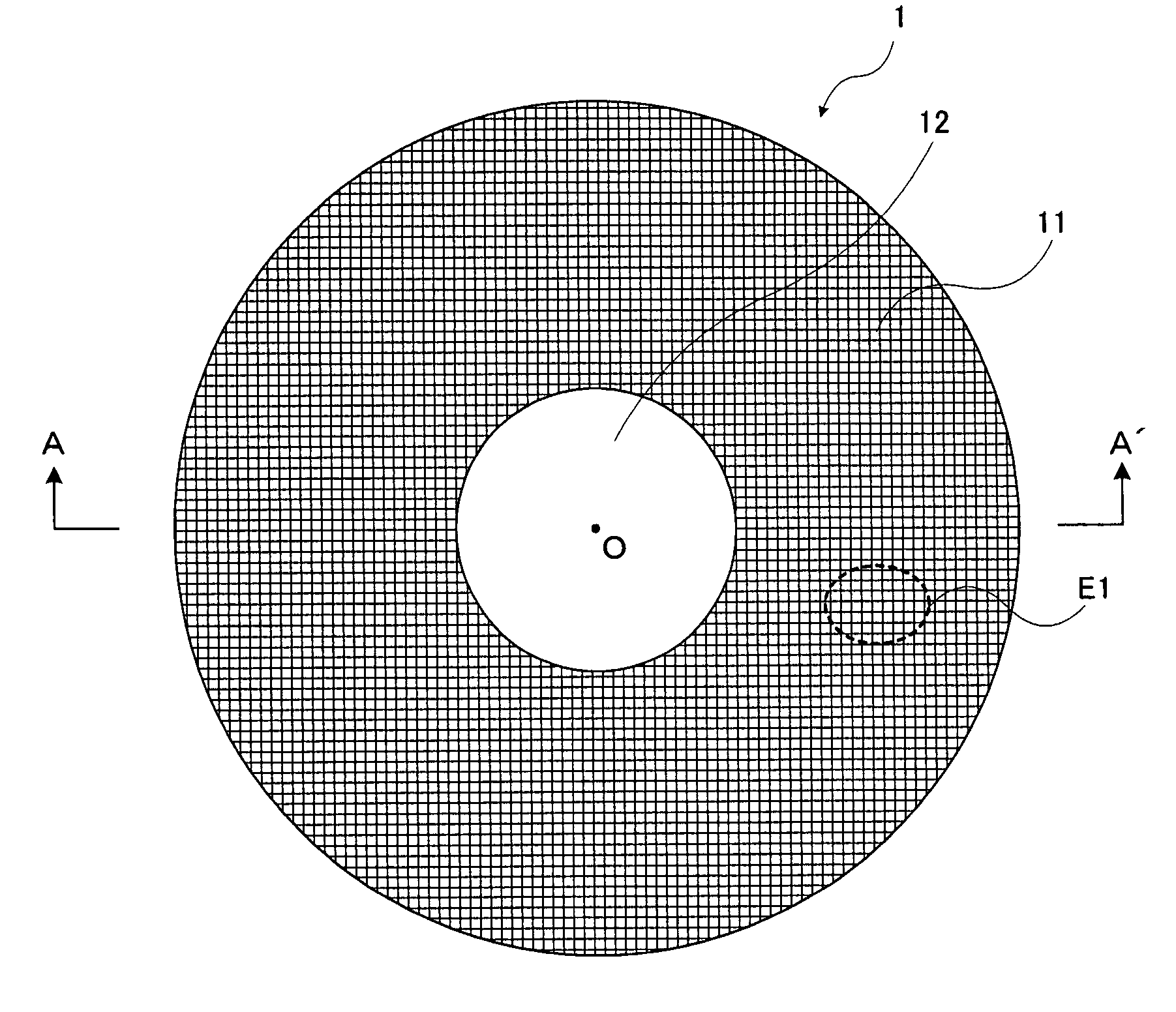
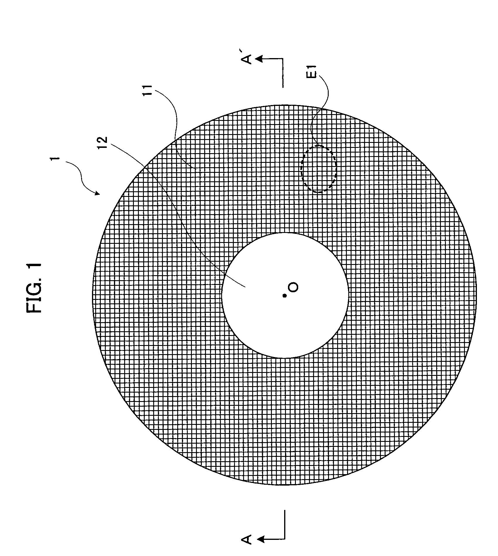
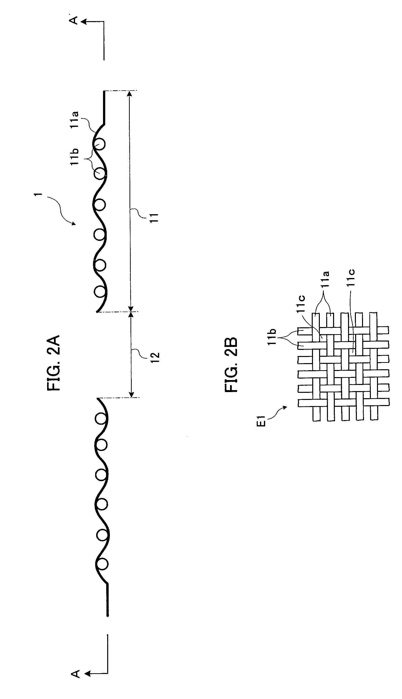
[0054] A damper 1 according to a first embodiment is made by pressing a material made by weaving metal wires into a net shape into an annular shape by a press device or the like. Referring to FIGS. 1 and 2A and 2B, a construction of the damper 1 according to the first embodiment will be explained. FIG. 1 shows a plan view of the damper 1. FIG. 2A is a sectional view taken along a cut line A-A′ in FIG. 1. FIG. 2B is a plane view of an enlarged part of a broken line area E1 of the damper 1 in FIG. 1.

[0055] The damper 1 is formed into an annular shape and has an elastic part 11 and an opening 12. A voice coil bobbin in a substantially cylindrical shape is inserted into the opening 12 formed into a circular shape. The elastic part 11 has a wire mesh structure in which a plurality of metal wires 11a extending substantially parallel with each other and a plurality of metal wires 11b extending in a substantially perpendicular direction to them are wo...

2nd embodiment

Construction of Damper (2nd Embodiment)

[0064] The elastic part 11 of the damper 1 according to the first embodiment has a small corrugated shape as shown in the sectional view in FIG. 2A. As described above, this is formed by weaving the respective metal wires 11a and the respective metal wires 11b. On the contrary, a damper 1a according to a second embodiment has a larger recessed and projected shape, namely, corrugated shape as compared with the elastic part 11 of the first embodiment. This is because the elastic part 11 having a small corrugated shape is pressed into a recessed and projected shape of a desired size by the press device. Such a recessed and projected shape is formed at the same time when the damper 1a is produced. Here, FIG. 3 shows a sectional view of the damper 1a according to the second embodiment thus formed. In FIG. 3, the same components as the damper 1 according to the first embodiment are given the same reference numerals and characters and the explanation ...

3rd embodiment

Construction of Damper (3rd Embodiment)

[0065] A damper 2 according to the third embodiment is made by the resin molding work (insert molding work) for the inner peripheral edge portion and the outer peripheral edge portion of the damper 1a according to the second embodiment. Referring to FIGS. 4 and 5, a construction of the damper 2 according to the third embodiment will be explained. FIG. 4 shows a plane view of the damper 2. FIG. 5 shows a sectional view taken along the cut line B-B′ in FIG. 4. In FIGS. 4 and 5, the same components as the damper 1 according to the first embodiment are given the same reference numerals and characters, and the explanation thereof will be omitted. Though illustration of the metal wires 11b extending in the perpendicular direction to the paper surface is omitted for convenience of illustration, the metal wires 11b actually extend in the substantially perpendicular direction to the metal wires 11a as in the first embodiment shown in FIGS. 2A and 2B.

[0...


PUM


Abstract

A damper having an annular elastic part is manufactured by stamping out a wire mesh material formed by weaving a plurality of metal wires into a net shape with a press device. The elastic part of the damper thus manufactured has a wire mesh structure. Thereby, a damper with high durability is obtained. Consequently, by applying this damper to the speaker device, the voice coil bobbin, a diaphragm and the like can be restrained/prevented from vibrating more than necessary even when an abnormal large signal is inputted into the speaker device.

Description

BACKGROUND OF THE INVENTION [0001] 1. Field of the Invention [0002] The present invention relates to a structure of a damper in a speaker device. [0003] 2. Description of the Related Art [0004] Recently, reflecting the demand of listeners to enjoy music and the like with powerful deep bass sound, increasingly larger signals tend to be inputted into a large-sized low sound reproducing speaker (for example, a subwoofer). Therefore, durability of a damper becomes a problem. [0005] Thus, in such a large-sized speaker for reproducing low sound, a plurality of dampers are provided, or a damper made of aramido (aromatic polyamide) fiber with high durability is provided, or a damper or the like made by bonding a plurality of sheets of aramido fiber is provided in order to restrain a voice coil bobbin, a diaphragm and the like from vibrating more than necessary when an abnormally large signal is inputted. [0006] However, when a plurality of dampers are provided, the size in the width directi...

Claims


Application Information

Patent Timeline
Patent Type & Authority Applications(United States)
IPC IPC(8): H04R9/04H04R9/02H04R25/00H04R31/00
CPCH04R9/043
Inventor MAEKAWA, KOJIISHIGAKI, TOSHIHIRO
Owner PIONEER CORP
Why Eureka
Try Eureka