Methods and apparatus for installation of VIV suppression during installation of marine pipeline

a technology for installing marine pipelines and installations, which is applied in mechanical equipment, vessel construction, transportation and packaging, etc., can solve the problems of large transverse current vibrations, large structural vibrations, and sometimes larger stresses, and achieve the effect of reducing the drag of marine elements

a technology for installing marine pipelines and installations, which is applied in mechanical equipment, vessel construction, transportation and packaging, etc., can solve the problems of large transverse current vibrations, large structural vibrations, and sometimes larger stresses, and achieve the effect of reducing the drag of marine elements

US20050254903A1Inactive Publication Date: 2005-11-17SHELL OIL CO

Image

  • Methods and apparatus for installation of VIV suppression during installation of marine pipeline
  • Methods and apparatus for installation of VIV suppression during installation of marine pipeline
  • Methods and apparatus for installation of VIV suppression during installation of marine pipeline

Examples


Embodiment Construction

[0042] The present invention is best understood by first making reference to the prior art, and understanding the problem of installing VIV suppression during an S-Lay installation of pipe.

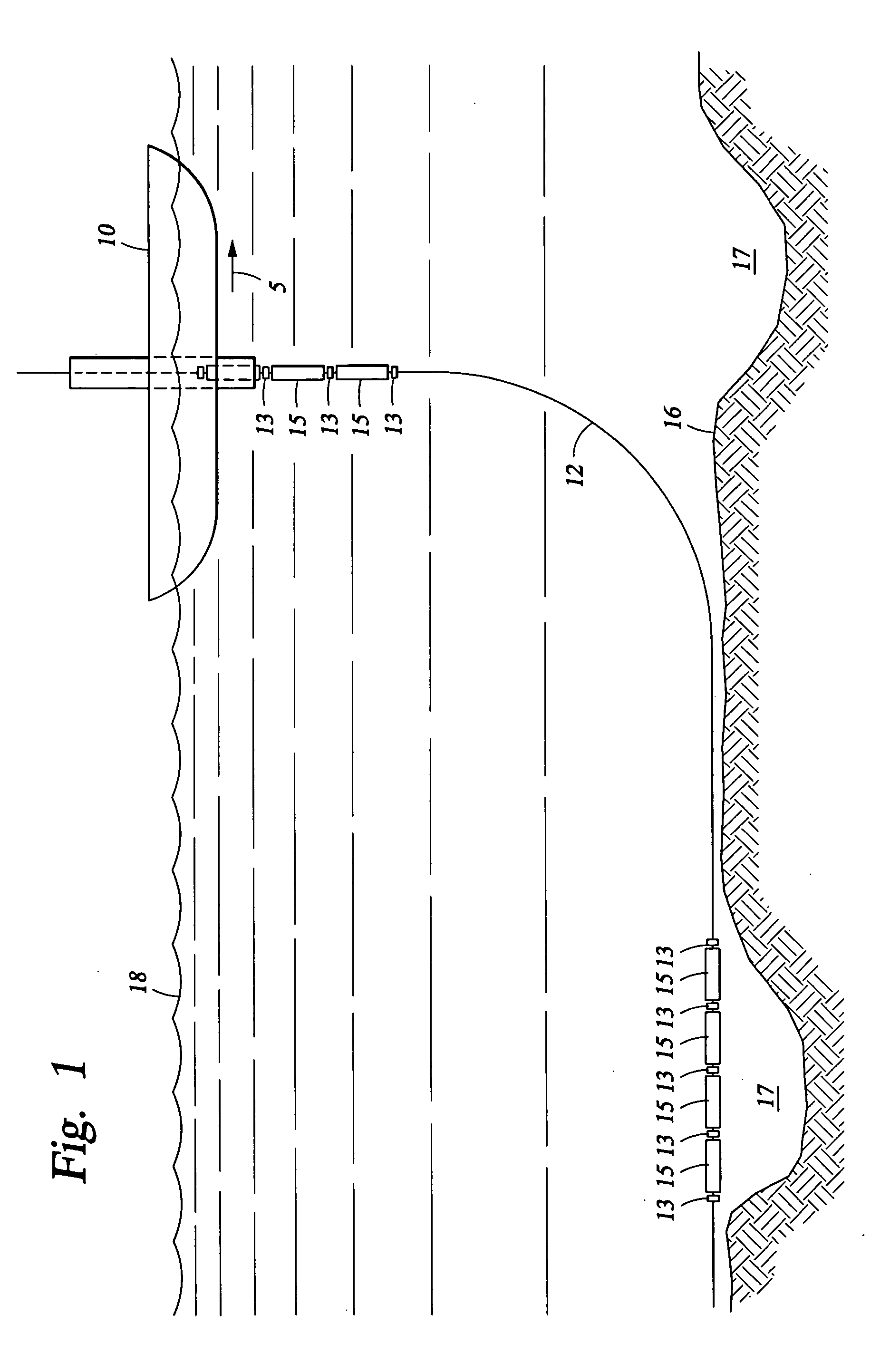
[0043] Referring to FIG. 1, there is shown a schematic representation of a prior art “J-Lay” installation of a subsea pipeline, showing vessel 10 moving in direction 5 at ocean surface 18, laying pipe 12 onto ocean floor 16. The name “J-Lay” comes from the “J” shape made by pipe 12 during installation. As shown, VIV suppression is being installed at those locations where pipeline 12 will span channels / trenches 17. Fairings 15 and collars 13 are very easily added during installation.

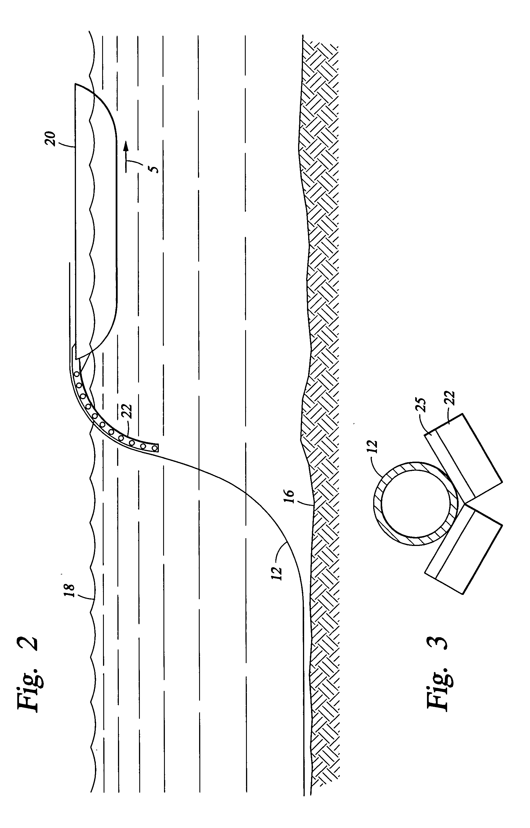
[0044] Referring now to FIG. 2, there is shown a schematic representation of a prior art “S-Lay” installation of a subsea pipeline, showing vessel 20 moving in direction 5 at ocean surface 18, laying pipe 12 utilizing stinger 22 onto ocean floor 16. The name “S-Lay” comes from the “S” shape made by pipe 12 during inst...


PUM


Abstract

Methods and apparatus for the installation of VIV suppression during the S-Lay installation of a subsea pipeline. A locking member will be interposed between a pipe and a fairing rotatably mounted on the pipe, sufficient to bias the fairing against rotating. Upon marine application, the locking member will degrade, thereby releasing the fairing.

Description

BACKGROUND OF THE INVENTION [0001] 1. Field of the Invention [0002] The present invention relates to apparatus, systems and methods for reducing vortex-induced-vibrations (“VIV”), current drag, low frequency drift oscillations due to random waves, and low frequency wind induced resonant oscillations. In another aspect, the present invention relates to apparatus, systems and methods comprising enhancement of VIV suppression devices for control of vortex-induced-vibrations, current drag, low frequency drift oscillations due to random waves, and low frequency wind induced resonant oscillations. In even another aspect, the present invention relates to apparatus, systems and methods comprising modified and improved performance fairings for reducing VIV, current drag, low frequency drift oscillations due to random waves, and low frequency wind-induced resonant oscillations. In still another aspect, the present invention relates to methods and apparatus for the “S-Lay” installation of pipe...

Claims


Application Information

Patent Timeline
17 Nov 2005
Publication
US20050254903A1
IPC
B63B21/50; B63B39/00; F15D1/10; F16L1/20
CPC
B63B21/502; B63B39/005; B63B2021/504; F16L1/20; F15D1/10; F16L1/18; B63B2035/442; F16L1/10
Inventors
MCMILLAN, DAVID W.; ALLEN, DONALD W.