Control valve for variable displacement compressor

a variable-discharge compressor and control valve technology, which is applied in the direction of pump control, positive-discharge liquid engine, machines/engines, etc., can solve the problems of inability to achieve sufficient improvement of compression efficiency, the flow rate of refrigerant circulating in the compressor cannot be reduced to a limited degree, and the compression efficiency is reduced. , to achieve the effect of improving compression efficiency and stable controllability

Inactive Publication Date: 2005-11-17
VALEO SYST THERMIQUES
View PDF10 Cites 21 Cited by
  • Summary
  • Abstract
  • Description
  • Claims
  • Application Information

AI Technical Summary

Benefits of technology

[0013] The present invention has been made in view of the above points, and an object thereof is to provide a control valve for a variable displacement compressor, which is capable of reducing the amount of refrigerant circulating within the compressor to thereby improve compression efficiency, while ensuring stable controllability.

Problems solved by technology

Consequently, in the variable displacement compressor using one of the above-described control valves, increased amount of refrigerant circulates therein, which inevitably causes degradation of compression efficiency.
Consequently, the flow rate of refrigerant circulating in the compressor can only be reduced to a limited degree, which makes it impossible to obtain sufficiently improved compression efficiency.
As a consequence, when the pressure in the crankcase rises excessively, gaseous refrigerant compressed in the crankcase cannot be reduced by changing the valve lift of the valve on the inlet side, and not until the suction pressure spontaneously becomes higher than a second set pressure with decrease in the displacement of the compressor to open the outlet-side refrigerant passage, does the pressure in the crankcase fall.
As described above, the latter control valve cannot ensure stable controllability.

Method used


Image

  • Control valve for variable displacement compressor
  • Control valve for variable displacement compressor
  • Control valve for variable displacement compressor

Examples


Embodiment Construction

[0030] The present invention will now be described in detail with reference to the accompanying drawings showing preferred embodiments thereof.

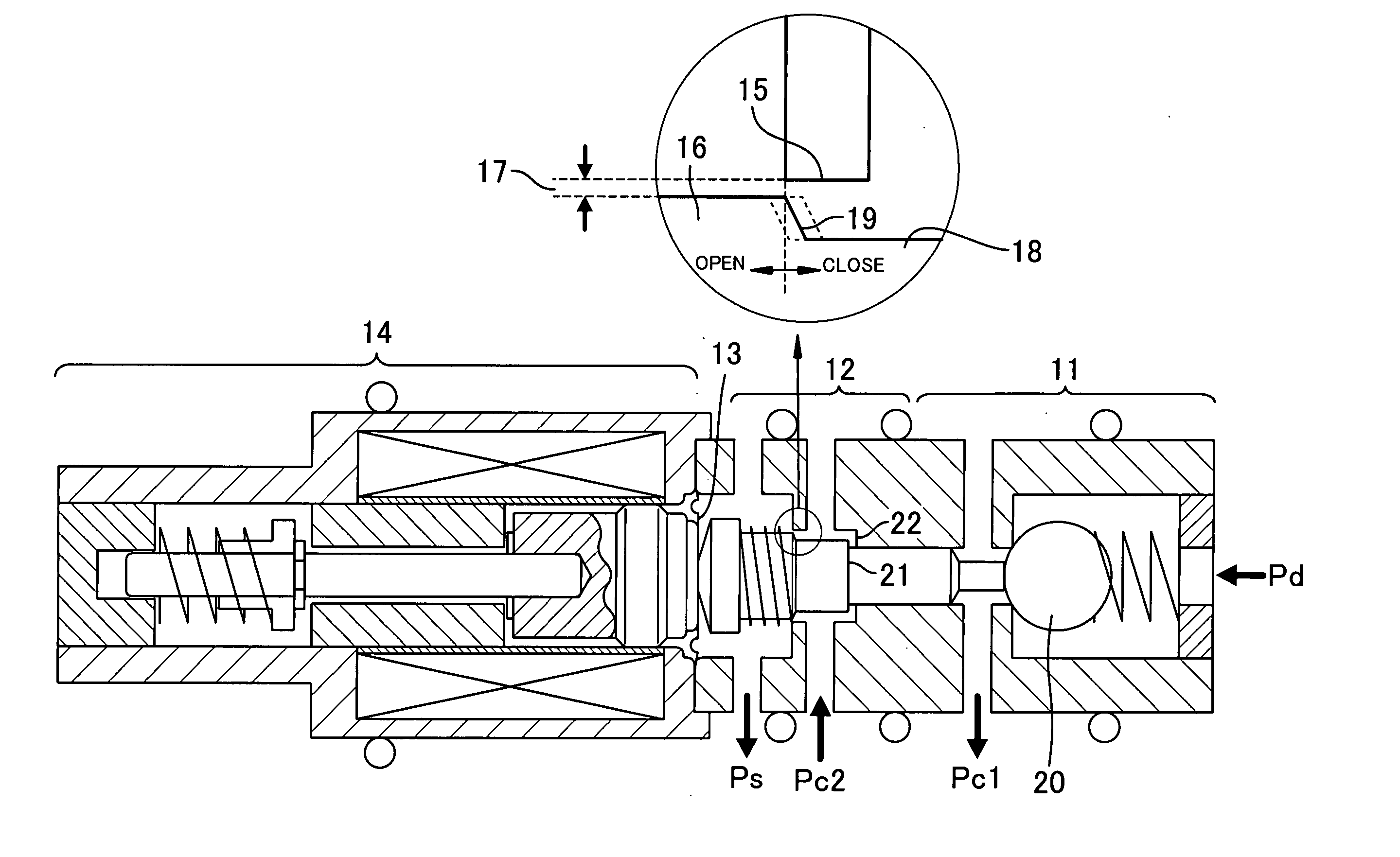
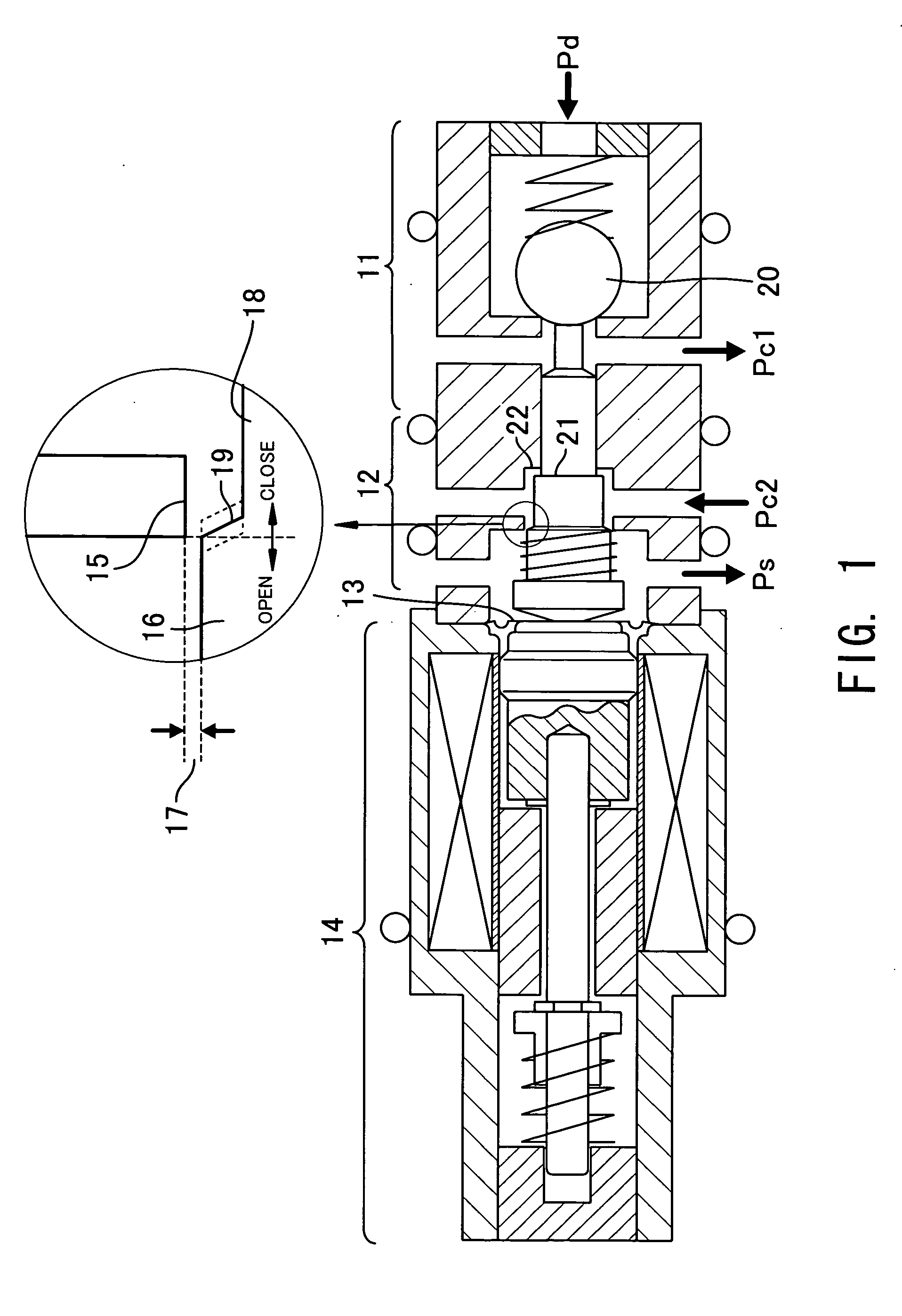
[0031]FIG. 1 is a conceptual view showing the arrangement of a control valve for a variable displacement compressor, according to the present invention.

[0032] The control valve for a variable displacement compressor, according to the present invention has a ball valve 11 forming a first valve, a spool valve 12 forming a second valve, a diaphragm 13 forming a pressure-sensing section, and a solenoid 14 forming a pressure-setting section, which are arranged in the mentioned order.

[0033] The ball valve 11 introduces refrigerant discharged at discharge pressure Pd from a discharge chamber of the variable displacement compressor, and controls the flow rate of the introduced refrigerant to supply the refrigerant at pressure Pc1 to a crankcase. The spool valve 12 introduces refrigerant delivered at pressure Pc2 from the crankcase, and controls th...


PUM


Abstract

In order to reduce the amount of refrigerant circulating within a variable displacement compressor to thereby improve compression efficiency, a control valve is configured to comprise a ball valve for controlling the flow rate of refrigerant flowing from a discharge chamber to a crankcase, a spool valve for controlling the flow rate of refrigerant flowing from the crankcase to a suction chamber, a diaphragm for sensing suction pressure, and a solenoid for setting the suction pressure, wherein the spool valve starts flow rate control after the ball valve is fully closed or nearly fully closed, and the ball valve starts flow rate control after the valve lift of the spool valve is minimized or nearly minimized. As a result, a region is almost eliminated in which the ball valve and the spool valve are both open simultaneously during switching of flow rate control between the ball valve and the spool valve, which makes it possible to minimize the flow rate of the refrigerant circulating within the compressor without contributing to a refrigerating operation, to thereby improve the efficiency of the compressor.

Description

[0001] This application is a continuing application, filed under 35 U.S.C. §111(a), of International Application PCT / JP2004 / 000505, filed Jan. 21, 2004.BACKGROUND OF THE INVENTION [0002] 1. Field of the Invention [0003] The present invention relates to a control valve for a variable displacement compressor, and more particularly to a control valve for a variable displacement compressor used in a refrigeration cycle of an automotive air conditioner. [0004] 2. Description of the Related Art [0005] The rotational speed of an engine as a drive source of an automotive air conditioner is not constant, and hence the air conditioner is required to be controlled such that refrigerating power thereof is held constant regardless of the engine rotational speed. To meet this requirement, a swash plate variable displacement compressor capable of changing the discharge amount of refrigerant is generally used in an automotive air conditioner. In the variable displacement compressor, a swash plate d...

Claims


Application Information

Patent Timeline
Patent Type & Authority Applications(United States)
IPC IPC(8): F04B27/18
CPCF04B27/1804F04B2027/1813F04B2027/1859F04B2027/1831F04B2027/1854F04B2027/1827F04B27/08F04B49/08
Inventor KAWAMURA, YUJIKOWADA, KAZUTAKAIRIE, KAZUHIROMUTA, SHUNJISATO, YOSHIE
Owner VALEO SYST THERMIQUES
Why Eureka
Try Eureka