Electromagnetic vibrating type diaphragm pump

a diaphragm pump, electromagnetic vibration technology, applied in the direction of positive displacement liquid engine, piston pump, liquid fuel engine, etc., can solve the problems of short life time of diaphragm pump, low efficiency, and difficulty in generating medium pressur

Inactive Publication Date: 2005-11-17
TECHNO TAKATSUKI
View PDF13 Cites 28 Cited by
  • Summary
  • Abstract
  • Description
  • Claims
  • Application Information

AI Technical Summary

Benefits of technology

[0033] Further, the electromagnetic diaphragm pump of the present invention is preferably a diaphragm

Problems solved by technology

However, the structure of a conventional diaphragm pump can generate only a low pressure of less than 50 kPa, therefore there is a problem that it is difficult to generate medium pressure (about 50 to 200

Method used


Image

  • Electromagnetic vibrating type diaphragm pump
  • Electromagnetic vibrating type diaphragm pump
  • Electromagnetic vibrating type diaphragm pump

Examples


embodiment 1

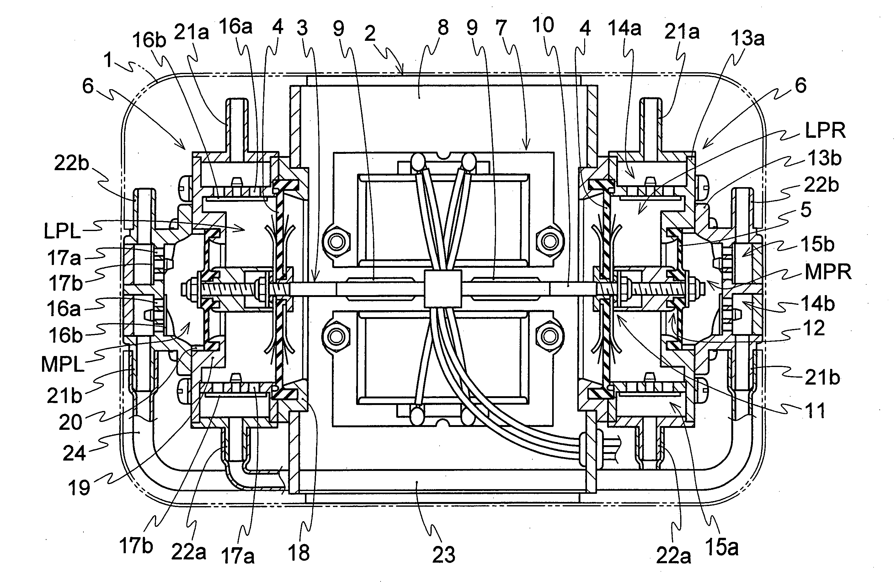
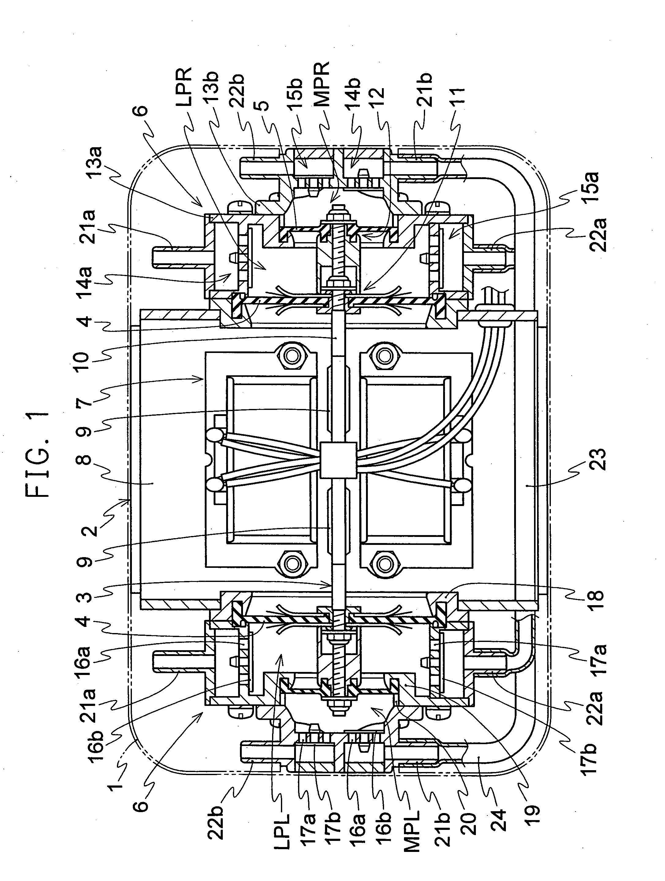
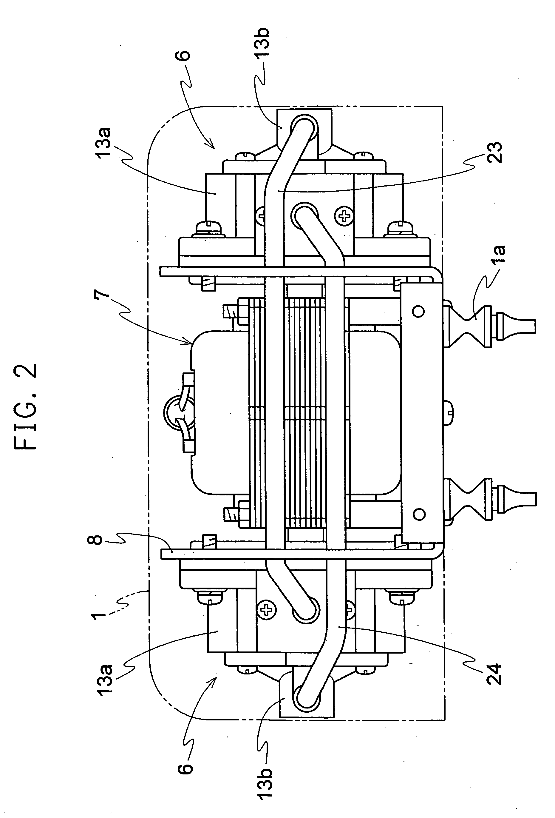
[0081] As shown in FIGS. 1 to 3, the electromagnetic vibrational diaphragm pump related to Embodiment 1 of the present invention is composed of a pump body cover 1, an electromagnet portion 2, a vibrator portion 3, disc shape diaphragms with a large diameter 4 and diaphragms with a small diameter 5 which are successively connected with both ends of said vibrator 3, and the pump casing portions 6 of said diaphragms with a large diameter 4 and diaphragms with a small diameter 5 which are fixed on the both end portions of the above-mentioned electromagnet portion 2. The above-mentioned electromagnet portion 2 is not specifically limited in the present invention, and in the present Embodiment 1, an article obtained by arranging in the frame 8 the electromagnet 7 consisting of one pair of E type iron cores and the winding coil portion wound thereto is used. The above-mentioned vibrator 2 is inserted in the cavity portion of the electromagnet portion 1 and is obtained by retaining 2 of ma...

examples 1 and 2

[0091] Then, the flow rate-pressure property of the pump at an applied voltage of 120 V and frequencies of 50 Hz and 60 Hz is illustrated. Firstly, relation between flow rate, Q and pressure, H was studied with respect to the pump related to Embodiment 1 in which the pump chamber at lower pressure side and the pump chamber at medium pressure side were connected in series. The result is shown in FIG. 8. In FIG. 8, the curve C1 is property at 50 Hz (Example 1) and the curve C2 is property at 60 Hz (Example 2). Then, relation between flow rate, Q and pressure, H was studied with respect to the pump at low pressure side which was piped in a condition in which with respect to the left and right pump chambers, the vent pipe is piped in parallel condition, namely in FIG. 1, one end (right end portion) of the vent pipe 23 was removed from the suction portion 21b and connected with the suction portion 21a of the pump chamber LPR; and the pump at medium pressure side which was piped in a cond...

embodiment 2

[0092] The above-mentioned Embodiment 1 is constituted so that air circuit is 2 circuits with 2 steps compression, but in Embodiment 2, all of the connection between the left and right pump portions is in series, and air circuit is one circuit with 4 steps compression. Namely, as shown in FIG. 9, 4 steps compression is formed by (air) →LPL→LPR→MPL→MPR (medium pressure), or (air) →LPL→LPR→MPR→MPL→(medium pressure), and 2-fold pressure of the pump related to the above-mentioned Embodiment 1 can be generated. However, flow rate becomes about one half. Thus, the pressure and flow rate (pump property) can be switched by changing the connection between the left and right pump portions.

[0093] Further, the connection shown in FIG. 9 as the above-mentioned connection between the left and right pump portions is inferior in the balance of left and right driving force (load) in comparison with the connection shown in FIG. 10, and the central point of vibration is deviated from the center of el...


PUM


Abstract

An electromagnetic vibrational diaphragm pump comprising an electromagnet portion having an electromagnet arranged in a frame, a vibrator which is supported in the electromagnet portion and equipped with a magnet, diaphragms with a large diameter and diaphragms with a small diameter which are successively connected with both ends of the vibrator, and the pump casing portions of the diaphragms with a large diameter and diaphragms with a small diameter which are fixed on the both end portions of the electromagnet portion, wherein the left and right pump casing portions have pump chambers respectively corresponding to the diaphragms with a large diameter and diaphragms with a small diameter. Medium pressure (about 50 to 200 kPa) can be generated.

Description

TECHNICAL FIELD [0001] The present invention relates to an electromagnetic vibrational diaphragm pump. More specifically, the present invention relates to an electromagnetic vibrational diaphragm pump which is mainly utilized for suction and disposal of air to an air mat and an air bed for interior, oxygen supply in a water vessel for fish farming, a home sanitation vessel and the like, or the sampling of test gas in pollution observation or the like. BACKGROUND ART [0002] There has been conventionally a diaphragm pump which is, for example, shown in FIG. 44, as an electromagnetic vibrational diaphragm pump sucking and discharging fluid utilizing the vibration of a vibrator which was equipped with a magnet based on electromagnetic interaction between an electromagnet and said magnet. [0003] The pump is composed of an electromagnet portion 151 having an electromagnet 151c consisting of an iron core 151a provided in a frame 150 and a winding coil portion 151b, a vibrator 153 equipped ...

Claims


Application Information

Patent Timeline
IPC IPC(8): F04B45/04F04B45/047
CPCF04B45/047F04B45/043F04B53/06F04B53/16F05B2210/12
Inventor OHYA, IKUOKOMURO, HIROKAZU
Owner TECHNO TAKATSUKI
Why Eureka
Try Eureka