
Method of applying a heat reflective coating to a substrate sheet

a technology of heat reflective coating and substrate sheet, which is applied in heat-proofing, natural mineral layered products, transportation and packaging, etc., can solve the problem that glass or plastic material per se of such panels is not particularly good thermal insulation, and achieve the effect of effective blocking and reflecting critical, increasing insulating efficiency, and resisting growth

Active Publication Date: 2005-11-17
PRITCHETT JOSEPH E
View PDF12 Cites 17 Cited by
  • Summary
  • Abstract
  • Description
  • Claims
  • Application Information

AI Technical Summary

Benefits of technology

[0029] In contrast, the coating material used with the present method serves primarily to reflect electromagnetic energy in certain bands or wavelengths in and around the infrared portion of the spectrum. This is accomplished by means of very fine, minute ceramic particles carried within the coating, with the particles comprising four different compounds ranging from five to 150 microns in size to effectively block and reflect the critical electromagnetic energy which transmits most of the heat energy from a radiant source (e.g., the sun). The combination of two different insulating principles in a single panel of material, results in a synergistic effect which increases the insulating efficiency particularly of the insulating panel which is coated according to the present method.

Problems solved by technology

The glass or plastic material per se of such panels is not a particularly good thermal insulator, but rather entraps and holds air within the panel to prevent significant circulation of the air, with the air serving as the insulating substance within the panel.

Method used


Image

  • Method of applying a heat reflective coating to a substrate sheet
  • Method of applying a heat reflective coating to a substrate sheet
  • Method of applying a heat reflective coating to a substrate sheet

Examples


Embodiment Construction

[0037] The present invention comprises various embodiments of a method of applying a heat reflective coating to a building construction panel, thereby increasing the insulation efficiency of the panel. The present invention also encompasses composite panels formed by applying the heat reflective coating to various types of building construction panels, as well. While the present invention is directed particularly to the coating of fibrous insulation batts with a heat reflective coating material, it may also be directed to the coating of other types of building construction panels as well.

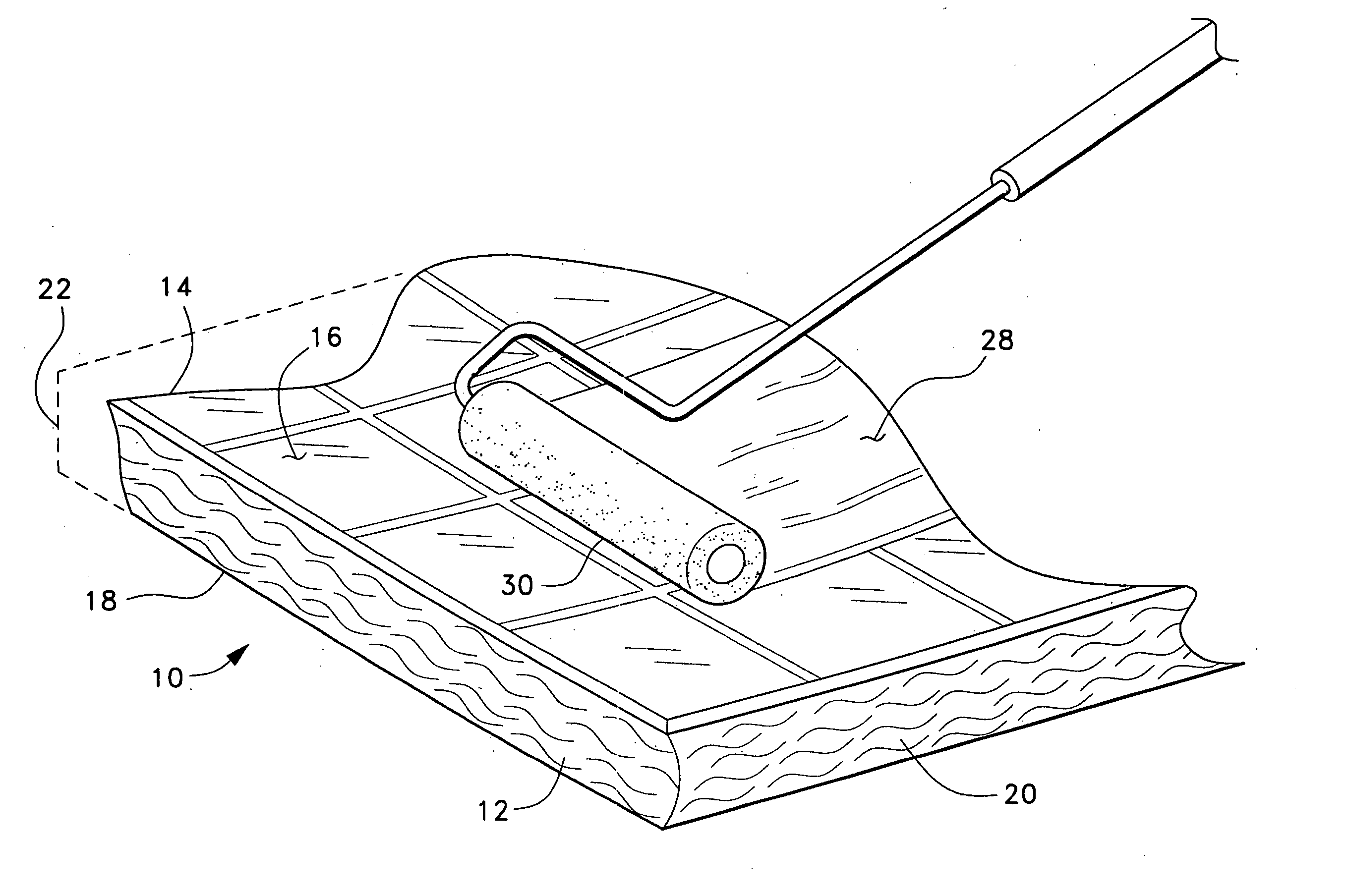
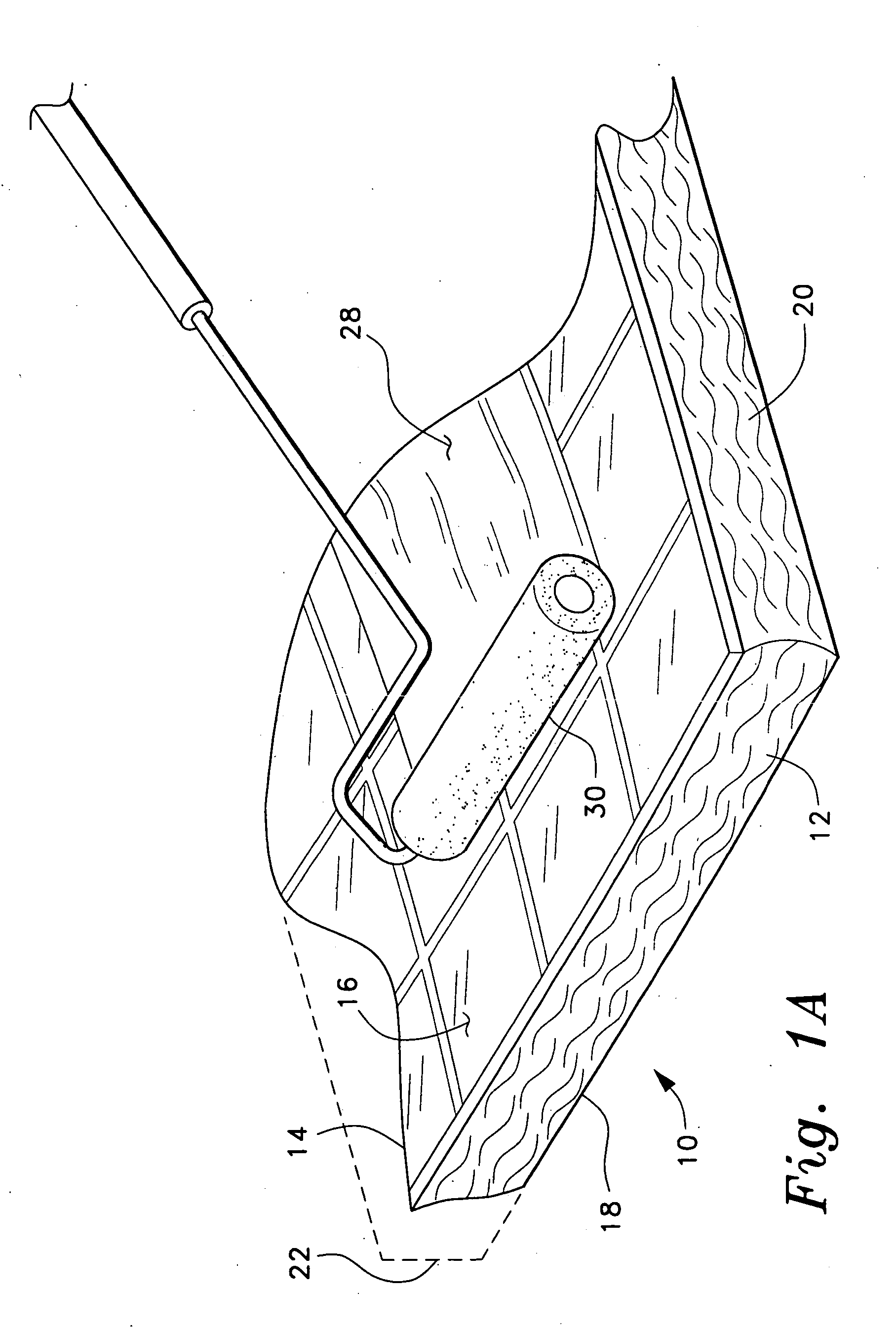
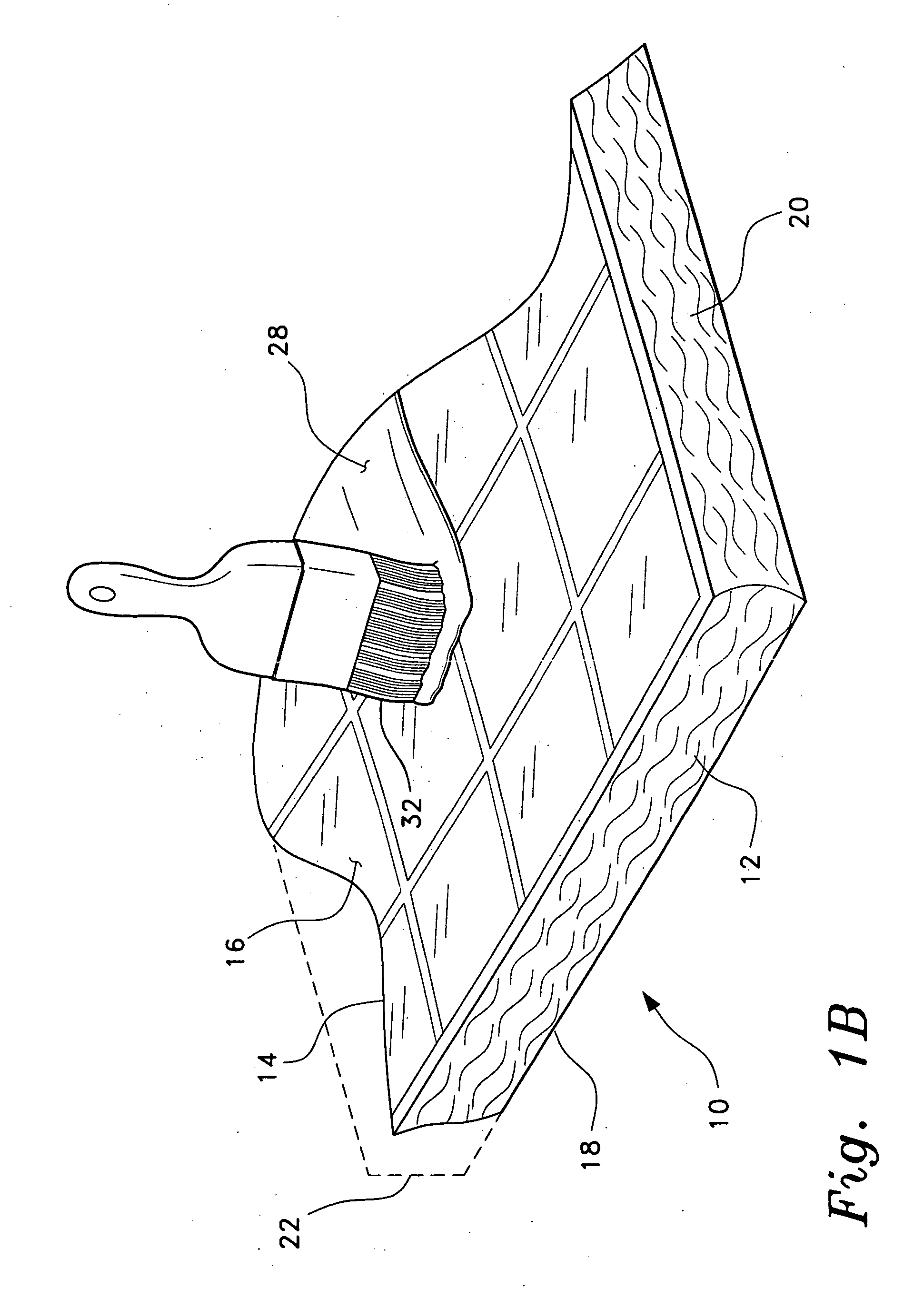
[0038]FIGS. 1A through 1C provide perspective views illustrating the process of coating various types of building construction panels with a heat reflective coating in accordance with the present invention. In FIGS. 1A through 2, a generally flat, planar panel or batt 10 of insulation material formed of loose fibrous material 12 (e.g., fiberglass, mineral wool, etc.) is illustrated. The batt 10 has...


PUM

PropertyMeasurementUnit
Timeaaaaaaaaaa
Efficiencyaaaaaaaaaa
Reflectionaaaaaaaaaa

Abstract

The method of applying a heat reflective coating to a substrate sheet of construction material is directed particularly to the coating of insulation material, such as fiberglass batts, at the time of manufacture. However, it may be applied to virtually any flat, planar sheet of material in order that the material may provide insulation as well as structural value. The present method provides numerous benefits. The insulation properties of the material are improved by the addition of the heat reflective coating thereon. Economies of scale are achieved by coating the materials at the time of manufacture, or at least at some centralized location. By completely encapsulating fibrous insulation with an impervious coating, the emission of irritant fiber particles from the insulation and corresponding health hazards are eliminated. Also, the efficiency of the insulation is improved by sealing out moisture when the insulation is completely encapsulated by the coating.

Description

BACKGROUND OF THE INVENTION [0001] 1. Field of the Invention [0002] The present invention relates generally to the covering of solid, dry materials with a coating applied as a liquid. More specifically, the present invention relates to the coating of sheet construction materials (e.g., fiberglass insulation batts, gypsum wallboard, plywood and chipboard sheets, etc.) with a relatively thin coating of a heat reflective material known by the trade name Super Therm® to improve the heat resistance and insulating capabilities of such materials in building construction. [0003] 2. Description of the Related Art [0004] Ever increasing energy costs have resulted in greater emphasis in energy efficient buildings and other structures over the years. Homes and other structures constructed much before the midpoint of the twentieth century were seldom provided with any significant insulation. At that time, the cost of the insulation material in comparison to energy costs, generally resulted in pa...

Claims


Application Information

Patent Timeline
IPC IPC(8): B32B1/04B32B29/02D06N3/00D06N3/14D06N7/00E04B1/76E04B1/80F16L59/08
CPCB32B29/02D06N3/0063D06N3/14E04B1/80E04B2001/7691Y10T428/237D06N2209/065D06N2201/082D06N2209/025D06N2209/067D06N2209/1671F16L59/08B32B17/065B32B19/046B32B2037/243B32B2307/304B32B2307/306B32B2315/085B32B2315/14B32B2317/122B32B2419/00
Inventor PRITCHETT, JOSEPH E.
Owner PRITCHETT JOSEPH E
Learn More