
Action rate control system

a control system and action rate technology, applied in the field of action rate control system, can solve the problems of affecting the operation of the action system of the firearm, and affecting the operation of the action system

Inactive Publication Date: 2005-11-24
REM TML HLDG LLC
View PDF49 Cites 15 Cited by
  • Summary
  • Abstract
  • Description
  • Claims
  • Application Information

AI Technical Summary

Benefits of technology

[0010] In another aspect of the invention, a gas operated firearm includes a barrel, a bolt assembly, an action system coupled to the bolt assembly, and a rate control cylinder coupled to the action system. The action system includes a sleeve assembly that is driven by a volume of combustion gases that are diverted from the barrel when a round of ammunition is fired. The rate control cylinder contr...

Problems solved by technology

However, a problem exists for firearms that are chambered for cartridges or shot shells, that, within a particular caliber or gauge, can have greatly varying ammunition offerings (i.e., firing magnum loads versus lighter target loads in shotguns, rifles and other types of firearms), such that controlling the energy and / or movement of the action system of the firearm solely by gas port volume is not practical.
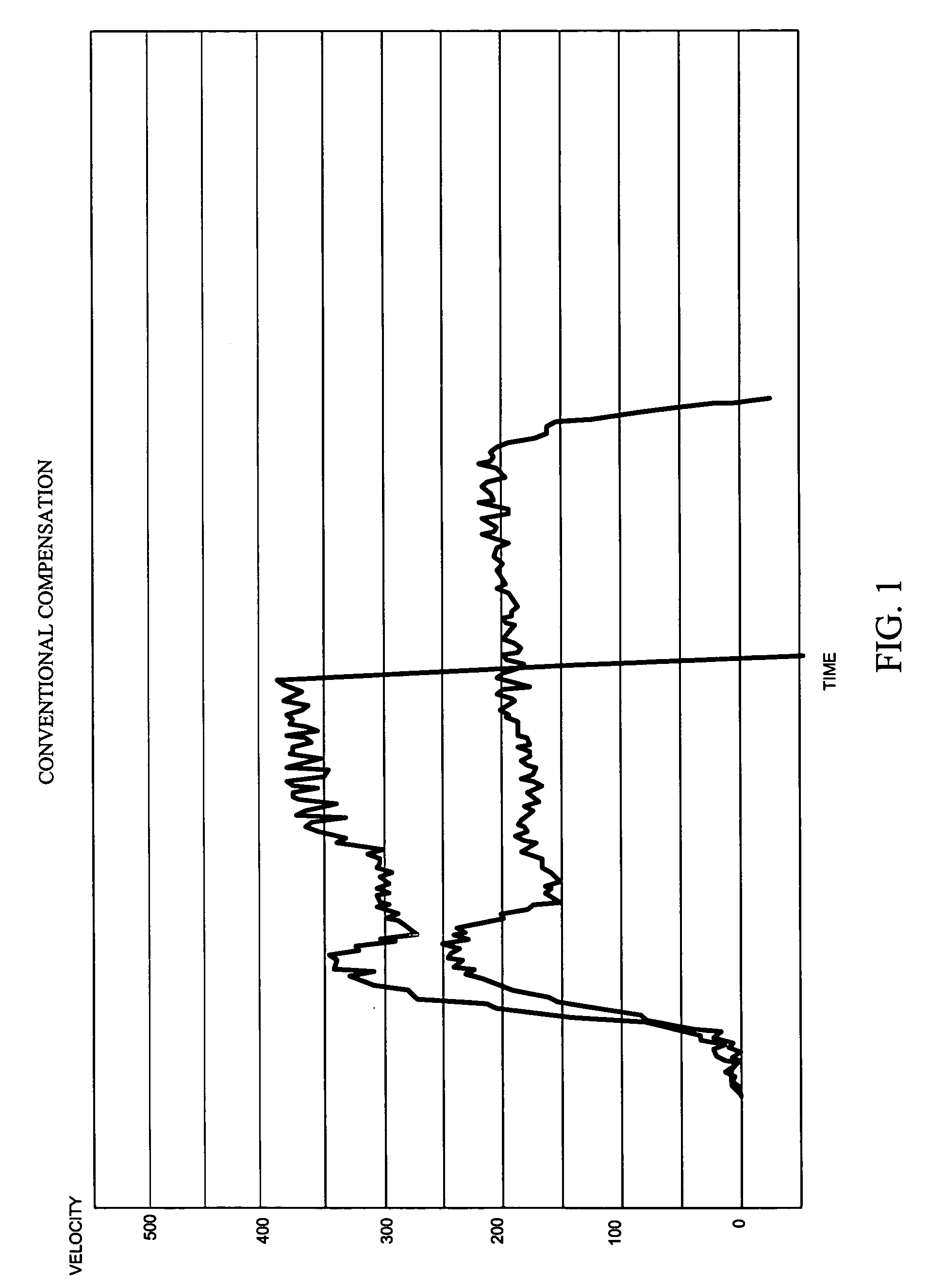
Although such compensation systems can reduce input energy (gas pressure), there still remains a substantial difference in the energy available to drive the action system of the firearm.
In other words, conventional compensation systems typically hit a peak and then remain fairly constant throughout the stroke or cycle of the firearm until it impacts the rear of the receiver and then an abrupt and potentially damaging stop occurs.
Upon firing, the velocities at which the action system is translated or moved affects the timing of the various mechanical interactions resulting from operation of the action system, and variations in such velocities can lead to potentially serious malfunctions of the firearm components.
Excess terminal velocity can lead to premature fatigue of various components of the firearm, while at full stroke, excess action system energy (velocity), such as generated by high energy rounds, must be consumed or addressed.
The consumption of excess energy typically is accomplished through a jarring mechanical impact as the bolt assembly and action system of the firearm are stopped at the rear limit of the action sleeve assembly.
Although buffers have been incorporated to soften the impact, the rapid decline in action system velocities still typically will impart substantial inertial loading on the components, potentially causing premature fatigue and failure when higher energy ammunition is shot in large quantities.

Method used


Image

  • Action rate control system
  • Action rate control system
  • Action rate control system

Examples


Embodiment Construction

[0017] The following description of the invention is provided as an enabling teaching of the invention in its best, currently known embodiment. Those skilled in the relevant art will recognize that many changes can be made to the embodiments described, while still obtaining the beneficial results of the present invention. It will also be apparent that some of the desired benefits of the present invention can be obtained by selecting some of the features of the present invention without utilizing other features. Accordingly, those who work in the art will recognize that many modifications and adaptations to the present invention are possible and may even be desirable in certain circumstances and are a part of the present invention. Thus, the following description is provided as illustrative of the principles of the present invention and not in limitation thereof, since the scope of the present invention is defined by the claims.

[0018] The present invention is designed to provide an ...


PUM


Abstract

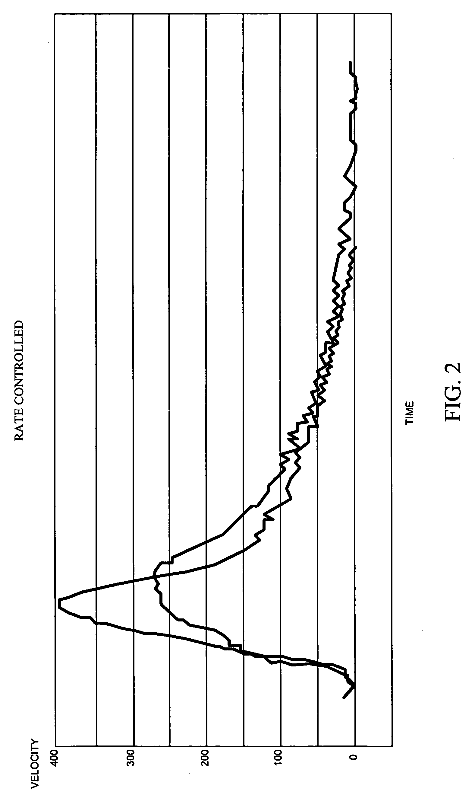
An action rate control system for a gas operated firearm that includes an action sleeve and an action rate control cylinder. The action sleeve moves in a rearward direction in response to a volume of combustion gases that are generated during firing of the firearm and diverted from the barrel of the firearm through gas ports. The action rate control cylinder is connected to the action sleeve by a linkage that controls movement and slowing of the action sleeve as it approaches a rear limit for its movement. The resistance force generated by the rate control cylinder is a function of the velocity of the action sleeve during its movement. In another aspect, a gas operated firearm includes a barrel, a bolt assembly, an action system coupled to the bolt assembly, and a rate control cylinder coupled to the action system. The action system includes a sleeve assembly that is driven by a volume of combustion gases that are diverted from the barrel when a round of ammunition is fired. The rate control cylinder controls a terminal velocity of the sleeve assembly being driven by the volume of combustion gases. A resistance force generated by the rate control cylinder is a function of the velocity of the bolt assembly during the bolt assembly's rearward movement. The velocity of the bolt assembly follows a controlled and gradual reduction as the energy load associated with the firing is absorbed by the rate control cylinder.

Description

CROSS-REFERENCE TO RELATED APPLICATION [0001] The present patent application is a formalization of a previously filed, co-pending provisional patent application entitled “Action Rate Control System”, filed Oct. 31, 2003, as U.S. patent application Ser. No. 60 / 516,583 by the inventors named in this patent application. This patent application claims the benefit of the filing date of the cited provisional patent application according to the statutes and rules governing provisional patent applications, particularly 35 U.S.C. § 119(e)(1) and 37 CFR §§ 1.78(a)(4) and (a)(5). The specification and drawings of the provisional patent application are specifically incorporated herein by reference.FIELD OF THE INVENTION [0002] The present invention generally relates to firearms, and in particular, to an action rate control system for controlling the action system for a gas operated firearm. BACKGROUND OF THE INVENTION [0003]“Gas operated” firearms, such as semi-automatic firearms, typically uti...

Claims


Application Information

Patent Timeline
IPC IPC(8): F41A5/18F41A25/02
CPCF41A25/02F41A5/18
Inventor KEENEY, MICHAEL D.JARBOE, MICHAEL BRENT
Owner REM TML HLDG LLC
Learn More