
Hybrid powertrain with engine valve deactivation

a technology of hybrid powertrain and engine valve, which is applied in the direction of machines/engines, gearing, non-mechanical valves, etc., can solve the problems of engine on and consuming fuel to drive accessories, and achieve the effects of reducing pumping losses, minimizing catalytic converter temperature loss, and conserving fuel

Active Publication Date: 2005-11-24
GM GLOBAL TECH OPERATIONS LLC
View PDF9 Cites 22 Cited by
  • Summary
  • Abstract
  • Description
  • Claims
  • Application Information

AI Technical Summary

Benefits of technology

[0007] An engine wherein all cylinders may be selectively rendered inoperative irrespective of crankshaft rotation provides significant benefits during hybrid powertrain operation. For example, in a preferred embodiment, the powertrain includes a controller that is configured to selectively activate and deactivate the cylinder valves. The controller is also configured to selectively cause a mode of engine operation wherein a first cylinder is in the operative condition while a second cylinder is in the inoperative condition during a first time period. During a second time period, the first cylinder is in the inoperative condition while the second cylinder is in the operative condition. During this mode of operation, which may occur, for example, when the electric motor is providing all motive power to propel the vehicle, fuel is conserved because not all cylinders are operative and pumping losses are reduced. The cylinders remain hot by alternating which of the cylinders is operative and firing, and which of the cylinders are inoperative.
[0008] In another preferred embodiment, a controller is sufficiently configured to selectively activate and deactivate the valves, and configured to cause a mode of engine operation in which every cylinder in the engine is in the inoperative condition by deactivating all the cylinder valves when a predetermined state exists, such as when the motor is supplying all motive power and during regenerative braking. The powertrain of the invention thus improves upon the prior art by enabling the elimination of the clutch between the rotor and the crankshaft found in the prior art because the rotor can turn the crankshaft without attendant pumping losses in the engine.
[0009] Accessories, such as a power steering pump and HVAC compressor, that may be connected to the crankshaft are driven by the motor turning the crankshaft when all engine cylinders are inoperative. Thus, the powertrain of the invention improves upon the prior art by enabling accessories operatively connected to the crankshaft to be driven by the motor when all engine cylinders are inoperative, thereby conserving fuel; the engine need not remain on merely to power accessories. The powertrain also minimizes loss of catalytic converter temperature compared to the prior art because cool gases are not being pumped through the exhaust system when all cylinders are inoperative.
[0010] The powertrain of the invention also eliminates the need for a separate starter motor and input clutch, as required by prior art powertrains, because the motor can start the engine by turning the crankshaft when at least one of the cylinders is operative.
[0011] Moreover, when the engine is commanded to supply motive power by the vehicle driver or an engine controller, the powertrain of the invention provides improved response compared to the prior art because the crankshaft may be driven by the motor when cylinders are inoperative without pumping losses, and thus the crankshaft may be continuously rotating at the same speed as the rotor and the input shaft. There would thus be no latency period during which the engine crankshaft and a torque converter must gain speed. If all engine cylinders are inoperative when commanded to supply motive power, the valves are simply activated so that intake and exhaust valves operate and the engine starts.

Problems solved by technology

Thus, the engine must be on and consuming fuel to drive the accessories, even when only the motor is propelling the vehicle or when the vehicle is at rest.

Method used


Image

  • Hybrid powertrain with engine valve deactivation
  • Hybrid powertrain with engine valve deactivation
  • Hybrid powertrain with engine valve deactivation

Examples


Embodiment Construction

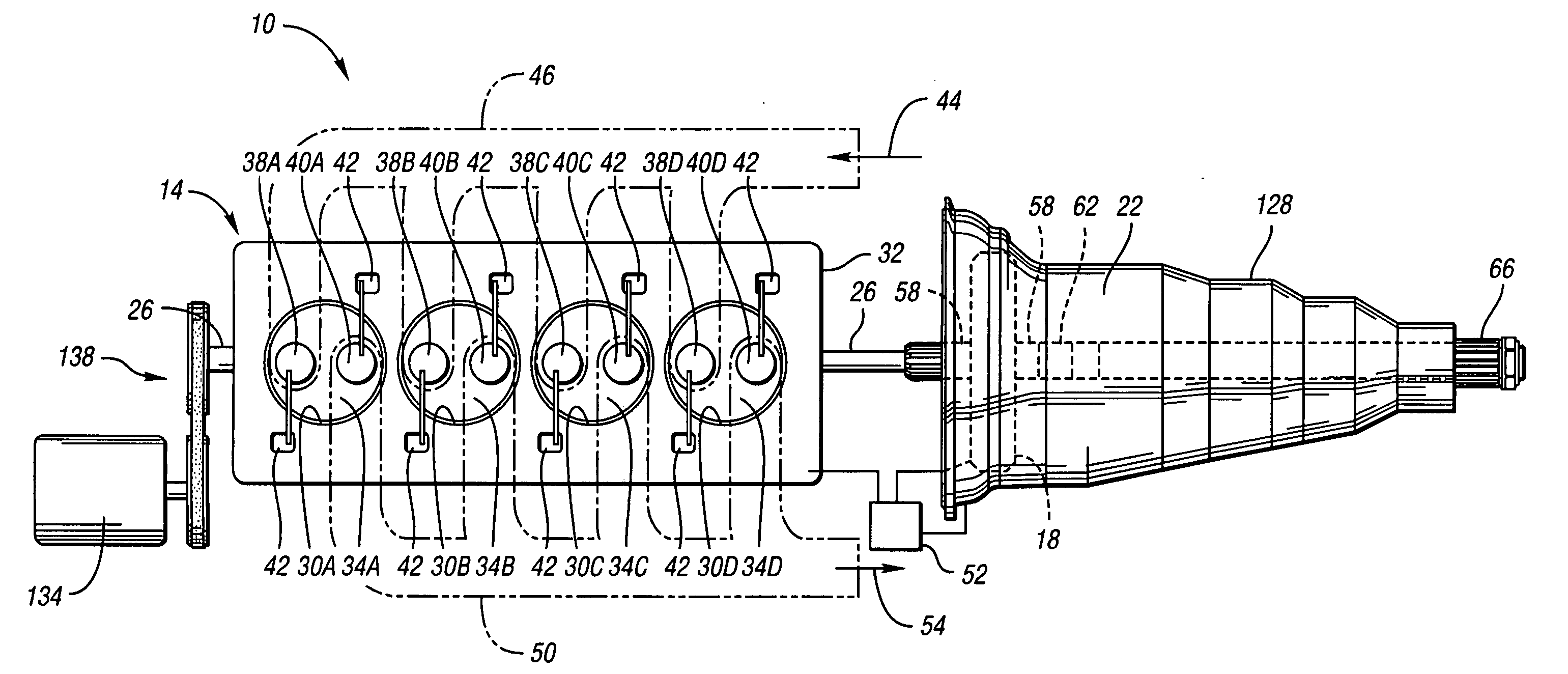
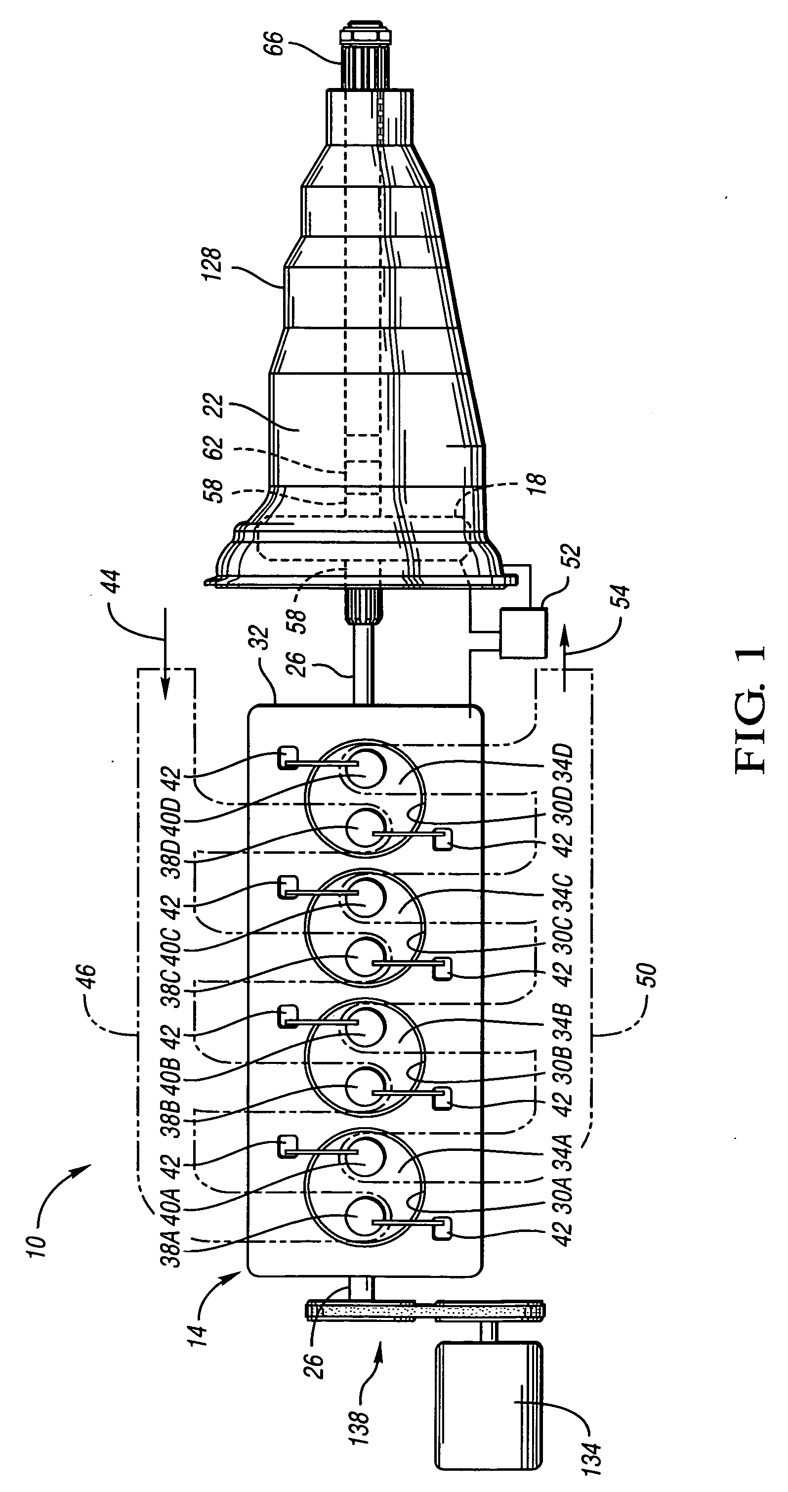
[0019] Referring to FIG. 1, a vehicle powertrain 10 is schematically depicted. The powertrain 10 includes an engine 14, an electric motor 18, and an automatic transmission 22. The engine 14 includes a rotatable crankshaft 26, a plurality of cylinders 30A-D formed in engine block 32, and a plurality of selectively activatable and deactivatable cylinder valves, namely intake valves 38A-D and exhaust valves 40A-D. The engine also includes a plurality of pistons 34A-D, each being translatable within one of the plurality of cylinders 30A-D.

[0020] Each of the intake valves 38A-D is movable between an open position in which gas (e.g., air 44) may be drawn into a corresponding cylinder 30A-D through an intake port during each intake stroke of the corresponding piston 34A-D, and a closed position to prevent gas from being drawn into the corresponding cylinder 30A-D. Each exhaust valve 40A-D is movable between an open position in which exhaust gas 54 can be exhausted from a corresponding cyl...


PUM


Abstract

A vehicle powertrain includes an engine and an electric motor in parallel hybrid combination. The engine includes a plurality of cylinders and a plurality of selectively deactivatable cylinder intake and exhaust valves so that every cylinder in the engine is characterized by an inoperative condition in which corresponding intake and exhaust valves remain in a closed position irrespective of crankshaft rotation. A controller is operatively connected to the valves and configured to advantageously control the valves and render cylinders inoperative. The powertrain enables the rotor of the motor to be continuously operatively connected to the crankshaft of the engine for unitary rotation therewith. The powertrain is preferably characterized by integrated friction launch wherein an active torque-transmitting mechanism controls vehicle launch.

Description

TECHNICAL FIELD [0001] This invention relates to hybrid vehicle powertrains that include an engine with a plurality of cylinders each having a plurality of selectively deactivatable valves operatively connected thereto. BACKGROUND OF THE INVENTION [0002] Prior art hybrid powertrains typically include an internal combustion engine, an electric motor, and a transmission. The crankshaft of the engine, the rotor of the motor, and the input shaft of the engine are selectively interconnected by various torque-transmitting mechanisms. These torque-transmitting mechanisms have been necessary in the prior art to disengage the engine from the motor and to disengage the engine and the motor from the transmission. [0003] More specifically, in a typical prior art hybrid powertrain, the crankshaft of the engine is selectively connected to the rotor of the motor by a clutch. When the clutch is engaged, the crankshaft and rotor rotate in unison; when the clutch is disengaged, the engine is disconne...

Claims


Application Information

Patent Timeline
Patent Type & Authority Applications(United States)
IPC IPC(8): B60K6/24F02D17/02B60K6/365B60K6/485B60W10/06B60W10/08B60W10/10B60W20/00F02B65/00F02D13/06F02D29/00F02D29/06F16H3/66
CPCB60K6/24Y10S903/917B60W10/06B60W10/08B60W10/115B60W20/00F02B65/00F16H3/663F16H3/666F16H2200/0052F16H2200/2023F16H2200/2097Y02T10/6226Y02T10/6286Y02T10/6295B60K6/485Y02T10/62F02D17/02
Inventor VAHABZADEH, HAMIDSAVAGIAN, PETER J.
Owner GM GLOBAL TECH OPERATIONS LLC
Features
  • Generate Ideas
  • Intellectual Property
  • Life Sciences
  • Materials
  • Tech Scout
  • Unparalleled Data Quality
  • Higher Quality Content
  • 60% Fewer Hallucinations
Learn More