Pressurized screen for screening a fibrous suspension and use thereof

a screening screen and fibrous suspension technology, applied in the direction of fat/resin/pitch/waxes removal in pulp, papermaking, chemistry apparatus and processes, etc., can solve the problems of increasing risk, increasing damage or wear, and almost always using wire scrapers

Inactive Publication Date: 2005-11-24
VOITH PATENT GMBH
View PDF4 Cites 3 Cited by
  • Summary
  • Abstract
  • Description
  • Claims
  • Application Information

AI Technical Summary

Benefits of technology

[0012] The present invention improves known pressurized screens so that a considerable part of the foreign particles can already be removed from the paper stock suspension before they reach the wire. Thereby in particular heavy particles encouraging wear and sensitive light particles should be removed at an early stage.
[0014] With the pressurized screen of the type mentioned, much more favorable flow conditions can be obtained through the measures according to the invention, which applies in particular to the inflow chamber. In general this is ring-shaped and is supplied with the fibrous suspension to be screened through an inflow attached tangentially, through which a rotational flow develops. As a result of the centrifugal forces thus generated, the heavy particles are centrifuged radially outwards so that they do not come into contact with the wire at all or hardly at all. They float in the direction of the inner wall of the housing and are in part dragged further by the suspension flow and in part transported by gravity into a part of the inflow chamber from which they can easily be removed. The wire scraper rotating radially inside the wire—thus on the accepted stock side—generates pressure and suction impulses in the accepted-stock chamber to clear the wire openings. The wire scraper thereby has a direction of rotation that is directed in an opposite manner to the direction of rotation of the rotating liquid ring located in the inflow chamber. This is advantageous since the scraper blades in interaction with the wire generate a reverse rotation flow in the inflow chamber, thus drive the suspension located in the inflow chamber in the direction that it already has from the inlet. The light particles are separated from the heavy particles by the centrifugal forces and move upwards along the wire and can easily be carried away. Due to the marked rotational flow also directly at the wire, the tendency of the light particles to adhere to it is slight. In this manner the separation effect of heavy particles and of light particles in the inflow chamber is considerably improved without additional expense in terms of equipment and with approximately the same energy consumption.

Problems solved by technology

Although the majority of heavy contaminants would not pass through the screen openings typically used anyway, thus would be rejected there, there is the danger of damage or wear when they come into contact with the wire.
This risk is further increased in that wire scrapers are almost always used which move past the wire very close to it at a relatively high speed.
Although this is effective, it is associated with additional expense.
This means that the particles rejected at the wire have a lower speed and cannot be collected by the wire scraper.
In particular damage by jamming metal parts between the wire and the wire scraper is highly unlikely.
Heavy particles cannot therefore reach the wire so easily due to the centrifugal forces.
Despite this progress, the operation of pressurized screens of this type is very problematic.
Thus it cannot be ruled out that in particular with suspensions with a high content of foreign particles, such as, e.g., have to be treated directly after the recovered paper slushing in the primary screening, heavy particles, e.g., metal pieces, glass fragments and stones, scrape along the wire and lead to increased wear.
Also light particles, in particular foams (Styrofoam) are not removed or at least not optimally and quickly.
With them there is the danger that they are broken up so much in the pressurized screen that they reach the accepted stock and it is hard to separate them out in the subsequent separation stages.

Method used


Image

  • Pressurized screen for screening a fibrous suspension and use thereof
  • Pressurized screen for screening a fibrous suspension and use thereof
  • Pressurized screen for screening a fibrous suspension and use thereof

Examples


Embodiment Construction

[0039] The particulars shown herein are by way of example and for purposes of illustrative discussion of the embodiments of the present invention only and are presented in the cause of providing what is believed to be the most useful and readily understood description of the principles and conceptual aspects of the present invention. In this regard, no attempt is made to show structural details of the present invention in more detail than is necessary for the fundamental understanding of the present invention, the description taken with the drawings making apparent to those skilled in the art how the several forms of the present invention may be embodied in practice.

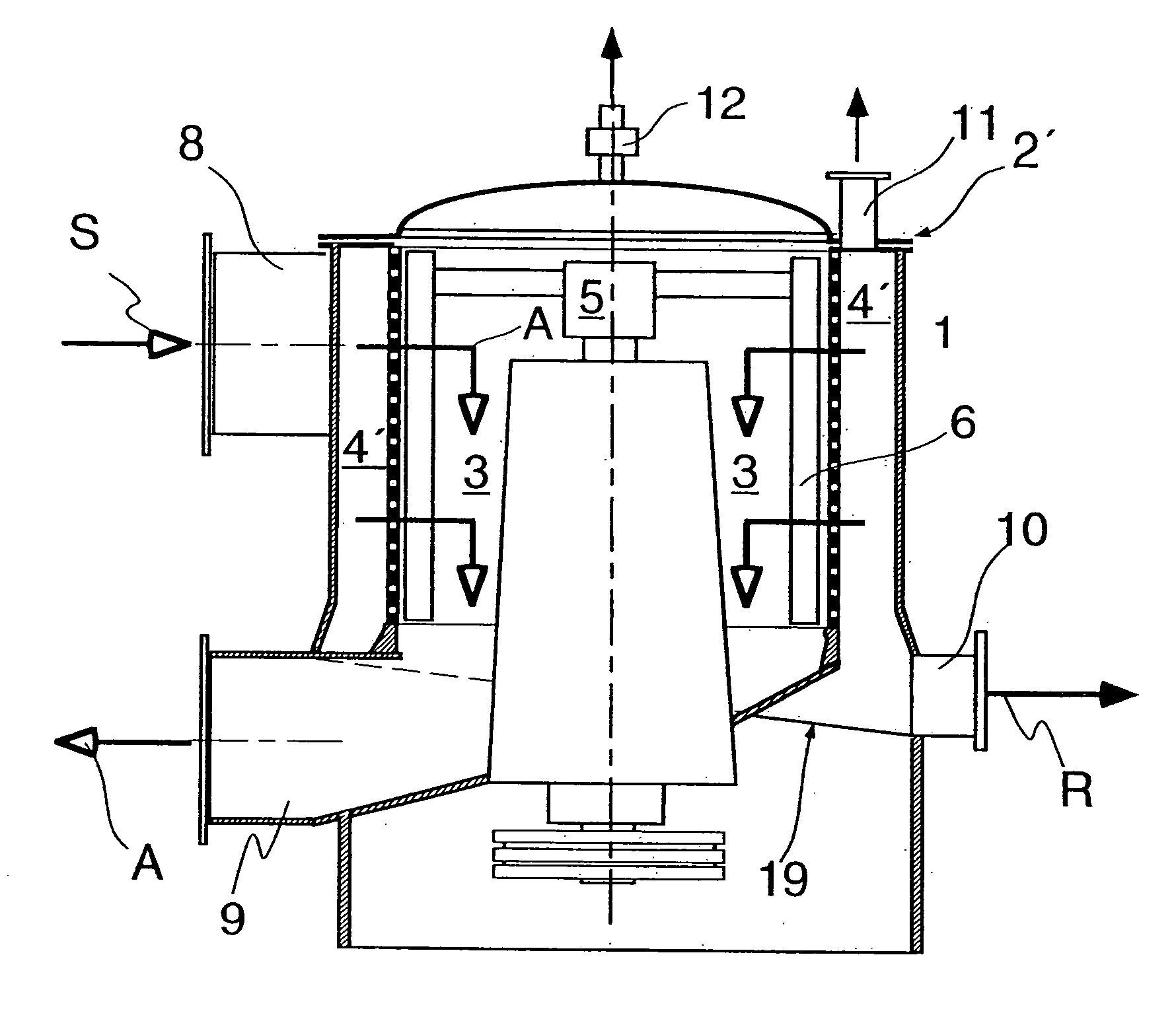
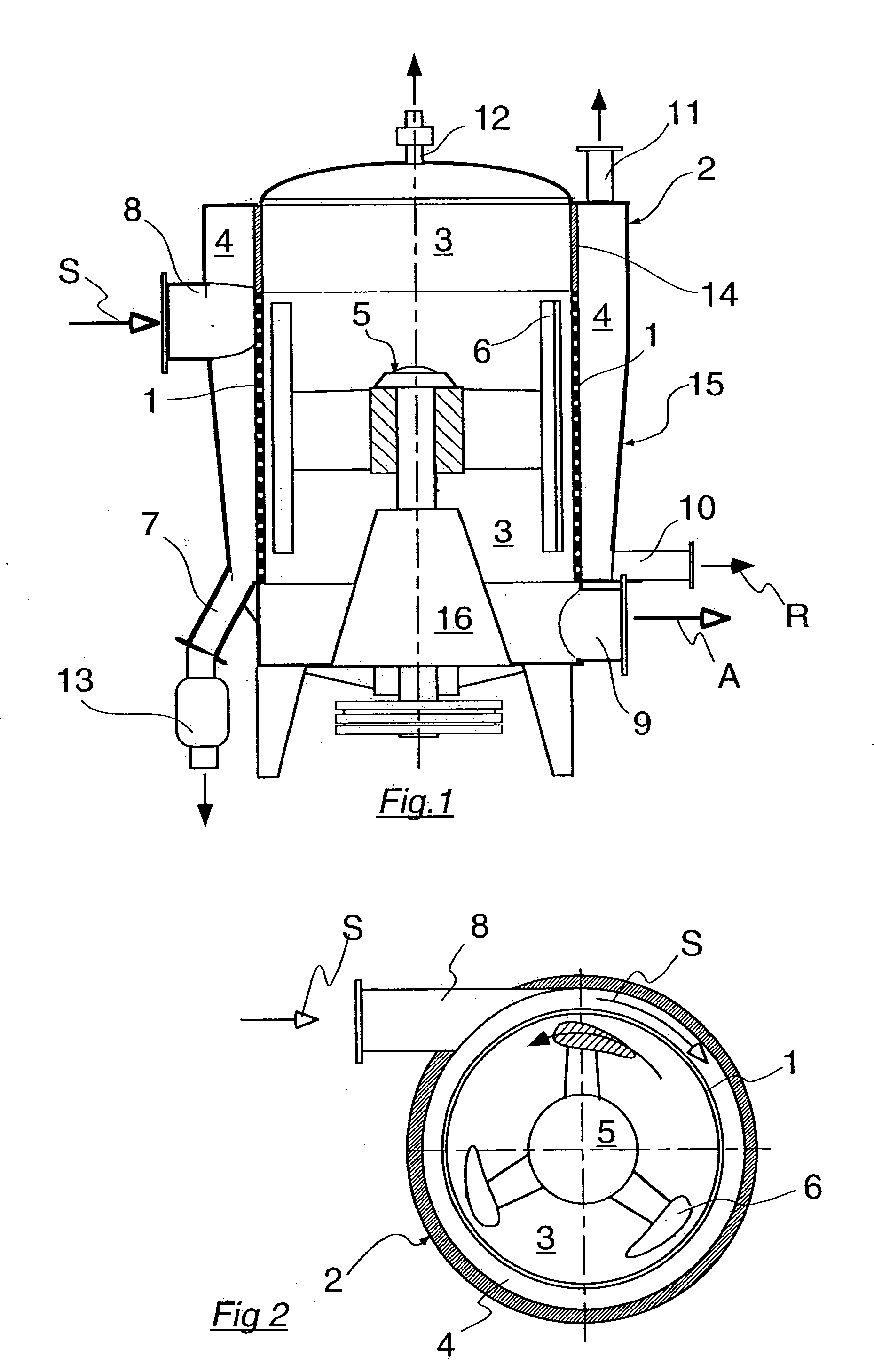
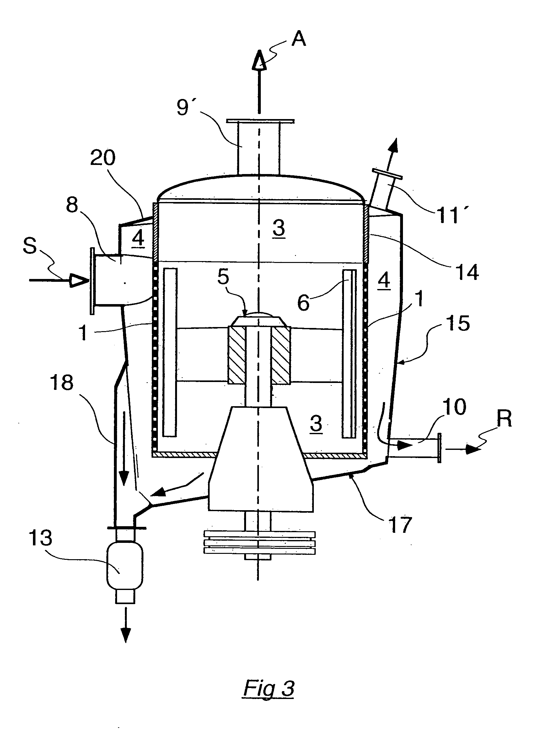
[0040]FIG. 1 shows a typical embodiment of the pressurized screen according to the invention. It contains in a housing 2 a wire 1 in the form of a cylindrical screen basket. In the position of use of the device, the center line of the wire 1 runs vertically here. It is therefore also referred to as a vertical screen. Th...


PUM

PropertyMeasurementUnit
diameteraaaaaaaaaa
diameteraaaaaaaaaa
sizeaaaaaaaaaa

Abstract

Pressurized screen and process for screening a fibrous suspension, in which the pressurized screen includes a housing and at least one wire arranged in the housing. The at least one wire has a plurality of openings and a center line of running essentially vertically. A tangential inflow is coupled to an inflow chamber, and an accepted-stock chamber is coupled to an accepted-stock outlet, such that the at least one wire being positioned in a flow path between the inflow chamber and the accepted-stock chamber. At least one reject outlet is provided, as well as a driven wire scraper located in the accepted-stock chamber driven in a circumferential direction opposed to an inflow direction of the suspension through the tangential inflow, and a light-particle outlet coupled to an upper part of the inflow chamber.

Description

CROSS-REFERENCE TO RELATED APPLICATIONS [0001] The present application claims priority under 35 U.S.C. §119 of German Patent Application No. 10 2004 025 149.5, filed on May 21, 2004, the disclosure of which is expressly incorporated by reference herein in its entirety. BACKGROUND OF THE INVENTION [0002] 1. Field of the Invention [0003] The invention relates to a pressurized screen for screening a fibrous suspension with at least one cylindrical or conical wire inserted in a housing. The center line of the wire runs essentially vertically in the position of use of the device and is provided with a plurality of wire openings, through which a part of the fibrous suspension fed through a tangential inflow into an inflow chamber can pass and reach an accepted stock chamber, to which an accepted stock outlet is attached. Another part of the suspension is rejected at the wire openings and is guided out of the screening device separately through at least one reject outlet as reject. In this...

Claims


Application Information

Patent Timeline
Patent Type & Authority Applications(United States)
IPC IPC(8): D21D5/02D21D5/16B03B5/00
CPCD21D5/026D21D1/34D21D5/16D21D5/22
Inventor RIENECKER, REIMUNDRIPPL, STEFANSCHWEISS, PETER
Owner VOITH PATENT GMBH
Why Eureka
Try Eureka